
Actuating mechanism with self-sealing rolling diaphragm

A technology for rolling diaphragms and actuators, applied in engine components, mechanical equipment, valve operation/release devices, etc., can solve the problems of unstable diaphragm effective area, unstable production, waste of energy, etc., to improve service life. and sealing reliability, long service life, overcoming the effect of easy air leakage

Inactive Publication Date: 2016-03-30
ZHEJIANG SANFANG CONTROL VALVE
View PDF6 Cites 0 Cited by
  • Summary
  • Abstract
  • Description
  • Claims
  • Application Information

AI Technical Summary

Problems solved by technology

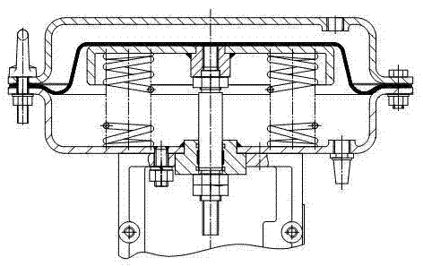
[0003] At present, with the development of the industrial industry, the application fields of valves are becoming wider and wider, and the requirements for valve adjustment accuracy and service life are getting higher and higher. The actuator in the valve structure plays a role in controlling the valve action. The known Traditional diaphragm actuators currently in use (see figure 1 ), due to structural reasons, the effective area of ​​the diaphragm is often unstable during operation. Leakage and rupture will occur after long-term use, resulting in unstable production, waste of energy, and serious shutdowns. Therefore, through the analysis of the diaphragm structure Based on feedback from on-site experience, we found that the leakage of traditional diaphragms generally occurs at the contact position between the diaphragm cover and the diaphragm. During the movement of the traditional diaphragm, the effective area changes because the diaphragm does not have a completely fixed trajectory. By making design changes to conventional diaphragms, we have developed an actuator with a self-sealing rolling diaphragm

Method used


Image

  • Actuating mechanism with self-sealing rolling diaphragm
  • Actuating mechanism with self-sealing rolling diaphragm
  • Actuating mechanism with self-sealing rolling diaphragm

Examples


Embodiment Construction

[0018] An actuator with a self-sealing rolling diaphragm of the present invention will be further described below through specific embodiments in conjunction with the accompanying drawings.

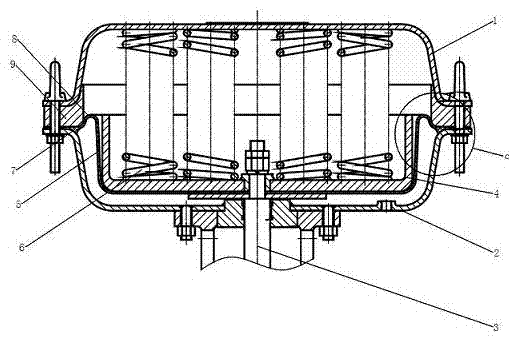
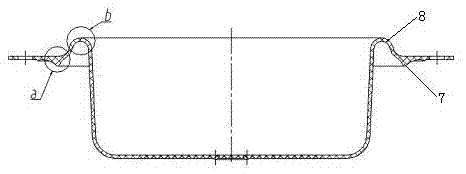
[0019] Such as Figure 1-Figure 6 As shown, an actuator with a self-sealing rolling diaphragm includes an upper diaphragm cover 1, a lower diaphragm cover 2, a push rod 3, a tray 4, a rolling diaphragm 5 and a spring 6, and the push rod 3 passes through The lower membrane cover 2, the top end of the push rod 3 is fixedly connected to the tray 4 and the rolling diaphragm 5, the bottom end of the push rod 3 is connected to the valve stem, and the upper surface of the rolling diaphragm 5 is matched with a tray 4, The edge of the rolling diaphragm 5 is fixed between the upper film cover 1 and the lower film cover 2, a number of springs 6 are arranged in cooperation between the tray 4 and the upper film cover 1, and the rolling diaphragm 5 is provided near the edge. There is a sealing lip 7, ...


PUM


Abstract

The invention discloses an actuating mechanism with a self-sealing rolling diaphragm. The actuating mechanism comprises an upper diaphragm cover, a lower diaphragm cover, a pushing rod, a tray, a rolling diaphragm and springs, wherein the pushing rod passes through the lower diaphragm cover; the top end of the pushing rod is fixedly connected to the tray and the rolling diaphragm; the bottom end of the pushing rod is connected with a valve rod; the tray is cooperatively arranged on the upper surface of the rolling diaphragm; the edge of the rolling diaphragm is fixed between the upper diaphragm cover and the lower diaphragm cover; a plurality of springs are cooperatively arranged between the tray and the upper diaphragm cover; a sealing lip side is arranged near the edge of the rolling diaphragm; a rolling ripple structure is arranged on the inner side of the sealing lip side. The actuating mechanism with the self-sealing rolling diaphragm is simple in structure, reasonable in design, long in service life, excellent in sealing effect, strong in stability, high in adjusting precision and low in cost.

Description

technical field [0001] The invention belongs to the technical field of valve actuators, in particular to an actuator with a self-sealing rolling diaphragm. Background technique [0002] Pneumatic film regulating valve is a kind of control device in the combination instrument of pneumatic unit. It is one of the important devices in the automatic adjustment system of the production process. It can be widely used in automatic adjustment and remote control of chemical industry, petroleum, metallurgy, electric power, light textile industry. At present, the commonly used pneumatic diaphragm regulating valve is mainly composed of a valve mechanism and an actuator, and the two are connected by a push rod connected in the middle. It is composed of connected brackets. A push rod that can slide up and down and connect the diaphragm and the valve stem of the valve mechanism is placed on the bracket. The membrane chamber in the actuator communicates with the external control air source....

Claims


Application Information

Patent Timeline
IPC IPC(8): F16K31/126
CPCF16K31/1262
Inventor 林锋杨佶凌飞章伟
Owner ZHEJIANG SANFANG CONTROL VALVE
Learn More