Special exhaust device for integrated cooker

An exhaust device and integrated stove technology, applied in the field of integrated stoves, can solve problems such as blockage of air outlet channels, oil stains, and reduced smoke exhaust effects, and achieve the effects of reducing sulfide, saving space, and being easy to use

Active Publication Date: 2016-03-30
QINGHAI TIANDILE TECH
View PDF7 Cites 1 Cited by
  • Summary
  • Abstract
  • Description
  • Claims
  • Application Information

AI Technical Summary

Problems solved by technology

[0008] The above-mentioned patent documents have the following deficiencies. When the gas flows in the air outlet channel, there will be oil stains attached to the inner wall of the air outlet channel. Long-term accumulation will block the air outlet channel and reduce the smoke exhaust effect.

Method used


Image

  • Special exhaust device for integrated cooker
  • Special exhaust device for integrated cooker
  • Special exhaust device for integrated cooker

Examples


Embodiment 1

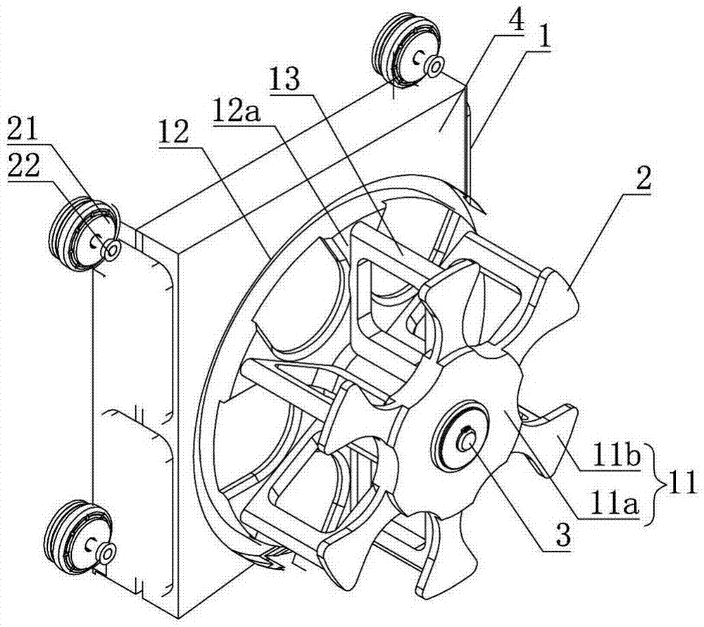
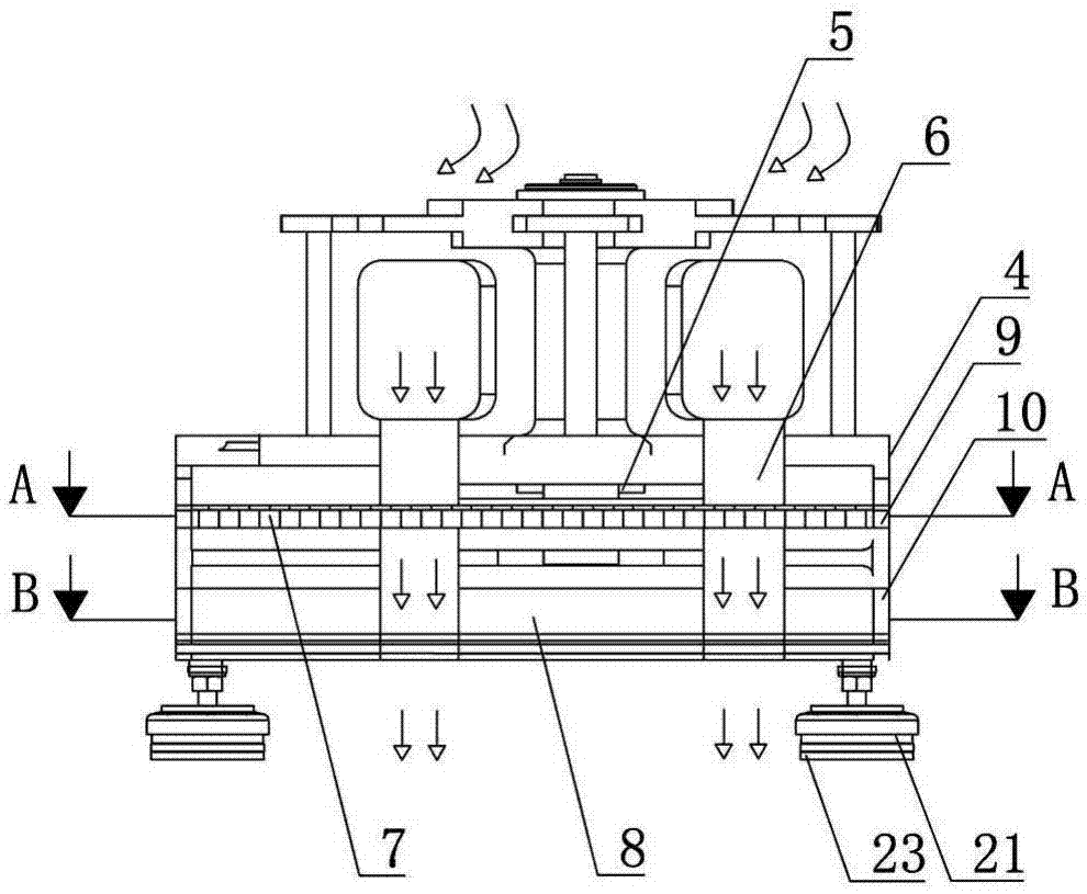
[0033] Such as figure 1 , figure 2 , image 3 As shown, the dedicated exhaust device for integrated stoves includes a mounting bracket assembly 1, an exhaust structure 2 located on the mounting bracket assembly 1, a movable shaft 3 for connecting the mounting bracket assembly 1 and the exhaust structure 2, and a mounting bracket The assembly 1 includes a rectangular frame 4. The central axis of the rectangular frame 4 is provided with a first groove 5 for inserting the movable shaft 3. The outer ring of the movable shaft 3 is provided with 6 exhaust channels 6. The rectangular frame 4 is arranged along the direction of the exhaust channel 6. A filter layer 7 is provided, a drainage grid frame 8 located below the filter layer 7, a first card slot 9 is provided on the inner wall of the rectangular frame 4, a second card slot 10 is located below the first card slot 9, and the filter layer 7 is movable Placed in the first slot 9, the upper end of the filter layer 7 is fixedly c...

Embodiment 2

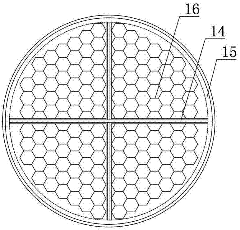
[0037] Such as figure 1 , figure 2 , image 3 , Figure 4 As shown, the dedicated exhaust device for integrated stoves includes a mounting bracket assembly 1, an exhaust structure 2 located on the mounting bracket assembly 1, a movable shaft 3 for connecting the mounting bracket assembly 1 and the exhaust structure 2, and a mounting bracket The assembly 1 includes a rectangular frame 4. The central axis of the rectangular frame 4 is provided with a first groove 5 for inserting the movable shaft 3. The outer ring of the movable shaft 3 is provided with 6 exhaust channels 6. The rectangular frame 4 is arranged along the direction of the exhaust channel 6. A filter layer 7 is provided, a drainage grid frame 8 located below the filter layer 7, a first card slot 9 is provided on the inner wall of the rectangular frame 4, a second card slot 10 is located below the first card slot 9, and the filter layer 7 is movable Placed in the first slot 9, the upper end of the filter layer 7...

Embodiment 3

[0044] Such as figure 1 , figure 2 , image 3 , Figure 4 As shown, the dedicated exhaust device for integrated stoves includes a mounting bracket assembly 1, an exhaust structure 2 located on the mounting bracket assembly 1, a movable shaft 3 for connecting the mounting bracket assembly 1 and the exhaust structure 2, and a mounting bracket The assembly 1 includes a rectangular frame 4. The central axis of the rectangular frame 4 is provided with a first groove 5 for inserting the movable shaft 3. The outer ring of the movable shaft 3 is provided with 6 exhaust channels 6. The rectangular frame 4 is arranged along the direction of the exhaust channel 6. A filter layer 7 is provided, a drainage grid frame 8 located below the filter layer 7, a first card slot 9 is provided on the inner wall of the rectangular frame 4, a second card slot 10 is located below the first card slot 9, and the filter layer 7 is movable Placed in the first slot 9, the upper end of the filter layer 7...


PUM


Abstract

The invention discloses a special exhaust device for an integrated cooker, relates to an integrated cooker, and aims at solving the problems that exhaust channels are liable to block and smoke exhaust effect is poor, existing in owners with small-family-type and apartment-type houses. The special exhaust device comprises an installation support assembly, an exhaust structure located on the installation support assembly, and a movable rotary shaft used for connecting the installation support assembly and the exhaust structure, wherein the installation support assembly comprises a rectangular frame; a central shaft of the rectangular frame is provided with a first groove used for inserting the movable rotary shaft; an outer ring of the movable rotary shaft is provided with 2-10 exhaust channels; the rectangular frame is provided with a filter screen layer along the direction of the exhaust channels, and a drainage screen frame located below the filter screen layer; and the inner wall of the rectangular frame is provided with a first clamping groove, and a second clamping groove located below the first clamping groove. According to the invention, through improving an exhaust structure, filter and guide are realized, and the rigid needs of the owners with small-family-type and apartment-type houses are much met.

Description

technical field [0001] The invention relates to an integrated cooker, in particular to a dedicated exhaust device for the integrated cooker. Background technique [0002] Integrated stove, also known as environmental protection stove or integrated environmental protection stove in the industry, integrated stove is a kitchen appliance that integrates multiple functions such as range hood, gas stove, disinfection cabinet, storage cabinet, etc. It has the effect of saving space and extracting oil fume Good, energy saving, low consumption and environmental protection. [0003] The integrated stove uses the principle of micro-aerodynamics, adopts the principle of deep well drainage or side suction drainage, and the principle of fluid negative pressure area generated by the lower exhaust air, so that the oil fume can be sucked downward like magic, and the oil fume can no longer be seen rising everywhere. phenomenon, the oil fume absorption rate is over 80%. The quality of the ex...

Claims


Application Information

Patent Timeline
IPC IPC(8): F24C15/20
CPCF24C15/2035F24C15/2042
Inventor 项韵男李兴隆
Owner QINGHAI TIANDILE TECH
Why Eureka
Try Eureka