Hand-held backscatter imager and its imaging method

An imaging method and backscattering technology, applied in the field of X-ray imaging, can solve the problems of long scanning time, low scanning efficiency and low image quality, and achieve the effect of reducing scanning time, improving image quality and increasing scanning time

Active Publication Date: 2019-02-19
TSINGHUA UNIV +1
View PDF7 Cites 2 Cited by
  • Summary
  • Abstract
  • Description
  • Claims
  • Application Information

AI Technical Summary

Problems solved by technology

[0003] In the backscatter application technology, the flying spot scanning mode is very classic and has been widely used, but it has a natural disadvantage: low scanning efficiency
At this time, the image quality and scanning time are in a dilemma. If the image quality is maintained, the extremely low scanning speed will inevitably test the smoothness and durability of the operator's movements at low speed, which will seriously affect the operating experience; The image quality will affect the accuracy of the image judgment results of the viewers
Usually, handheld backscatter imagers cannot require the operator to maintain a long scan time, so low image quality is the result in most cases

Method used


Image

  • Hand-held backscatter imager and its imaging method
  • Hand-held backscatter imager and its imaging method
  • Hand-held backscatter imager and its imaging method

Examples


Embodiment 1

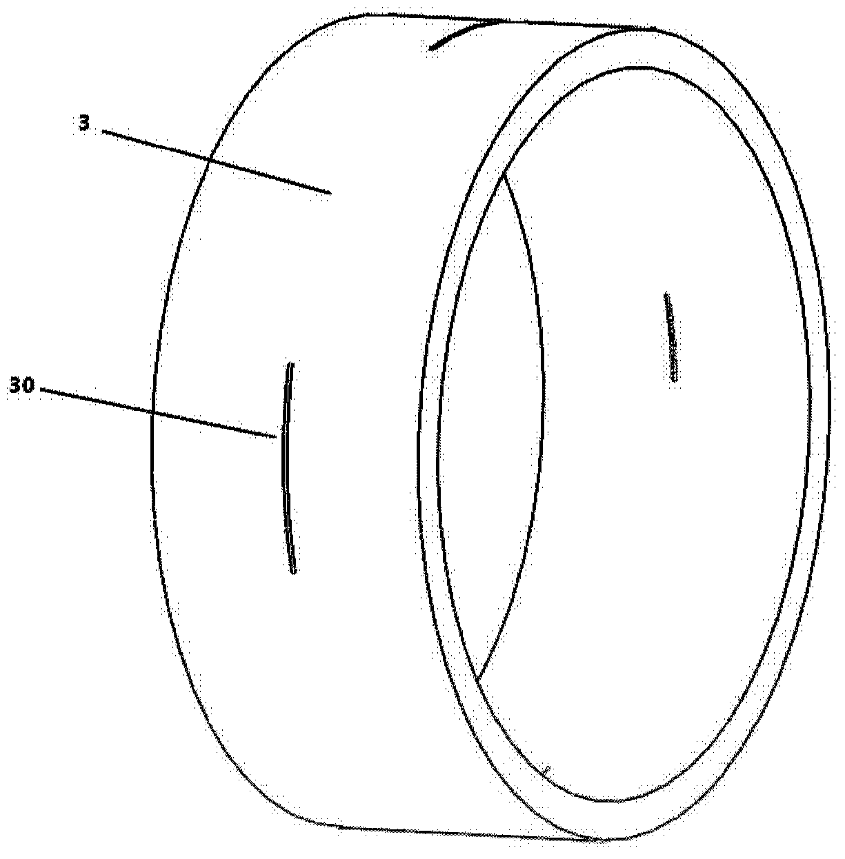
[0075] The X-ray passage area 30 on the modulator 3 adopts a slotting method.

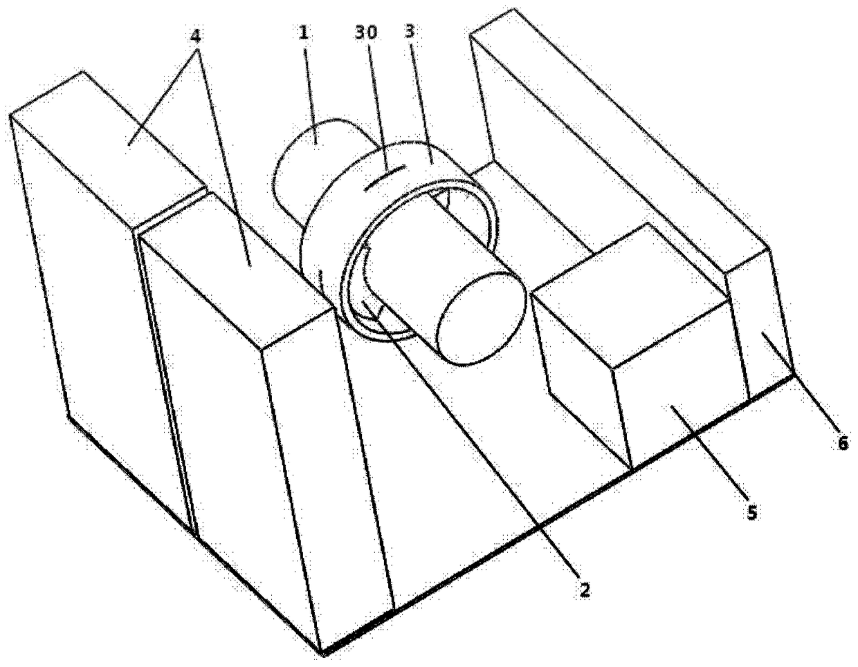
[0076] The aspect ratio n of the collimating slit on the collimator 2 is designed as a narrow and long through groove 31 form through the area 30, and the aspect ratio is m, 2≤m

[0077] When the modulator 3 rotates, the signal collected by the detector 3 is set as S 1 , S 2 ,...,S n , and the pixel value for display on the final image is set to P 1 ,P 2 ,...,P n , then the calculation formula of the pixel value is as follows.

[0078]

Embodiment 2

[0080] The X-ray passage area 30 on the modulator 3 adopts an opening method.

[0081] The aspect ratio n of the collimating slit on the collimator 2 is designed as a narrow and long through-hole column 32 formed by connecting a series of through-holes through the area 30, and the number of through-holes is m, 2≤m

[0082] When the modulator 3 rotates, the signal collected by the detector 3 is set to S 1 , S 2 ,...,S n , and the pixel value for display on the final image is set to P 1 ,P 2 ,...,P n , the calculation formula of the imaging algorithm is as follows.

[0083]

Embodiment 3

[0085] The X-ray passage area 30 on the modulator 3 adopts another slotting method.

[0086] The aspect ratio n of the collimating slit on the collimator 2 is designed as a narrow and long through groove 31 by the region 30, and a "short tail" groove 310 is added at the end along the reverse direction of rotation (that is, there is a shorter diameter end part 310), the length of the "short tail" groove 310 is equal to the width of the narrow and long through groove 31, and the width is smaller than the width of the narrow and long through groove 31, and the proportional coefficient is α (α<1). The combined total length-to-width ratio m of the long and narrow through groove 31 and the “short tail” groove 310 is 2≦m

[0087] When the modulator 3 rotates...


PUM


Abstract

The present invention provides a hand-held backscatter imager, comprising: an X-ray source for generating X-rays; at least one collimator for collimation of X-rays; A modulator that rotates with the X-ray source, on which at least one X-ray passing region is formed for the X-ray beam corresponding to more than one imaging image pixel to pass through; a detector, the detector is configured to receive The X-ray beam modulated by the detector is scattered by the object to be inspected to obtain scattered X-rays, and generate corresponding scattered signals; and a controller configured to obtain angle information of the X-ray passing area and scattered signals from the detector. Correspondingly, the present invention also provides a backscatter imaging method. The handheld backscatter imager and its imaging method provided by the present invention solve the contradictory problem of image quality and scanning time through a special "flying line" scanning mode.

Description

technical field [0001] The present invention relates to the application field of X-ray imaging, in particular to the backscatter detection imaging of objects and its imaging method. The objects here can be luggage, vehicles, building walls and various types that need to identify the internal structure and the safety of internal items. objects. Background technique [0002] In backscatter detection imaging applications, according to the characteristics of backscatter signals, the most commonly used scanning method is flying-spot scanning, that is, the ray is modulated and collimated to become a ray pencil beam (flying spot) that is quickly scanned point by point in the first dimension. The object to be inspected; the plane of the ray pencil beam moves with the detector along the second-dimensional direction relative to the object to be inspected; the second-dimensional motion speed is much lower than the first-dimensional motion speed, and the second-dimensional direction is ...

Claims


Application Information

Patent Timeline
Patent Type & Authority Patents(China)
IPC IPC(8): G01N23/203
CPCG01N23/203G01N2223/3302G01N2223/301G01T7/00G01V5/0025G01N2223/3301
Inventor 陈志强李元景赵自然吴万龙唐乐金颖康王璞
Owner TSINGHUA UNIV
Why Eureka
Try Eureka