Imaging lens, iris imaging module and iris identification device

An imaging lens and lens technology, which is applied in the field of biometrics, can solve problems such as complex structure, large volume, and poor imaging quality, and achieve the effects of good imaging quality, high imaging quality, and convenient assembly

Active Publication Date: 2016-03-30
深圳眼神智能科技有限公司
View PDF8 Cites 6 Cited by
  • Summary
  • Abstract
  • Description
  • Claims
  • Application Information

AI Technical Summary

Problems solved by technology

[0003] The existing iris collection optical system can be divided into: zoom optical system and fixed focus optical system, among which the zoom optical system is large in size, complex in structure, high in cost and difficult to assemble, such as: the patent CN200810071474. The compensation zoom lens is composed of more than a dozen lenses; the fixed-focus optical system has simple structure, low cost and convenient installation, such as: the iris recognition device in Japanese patent JP2004-167046, its acquisition lens is composed of two lenses and filters,

Method used


Image

  • Imaging lens, iris imaging module and iris identification device
  • Imaging lens, iris imaging module and iris identification device
  • Imaging lens, iris imaging module and iris identification device

Examples


Embodiment 1

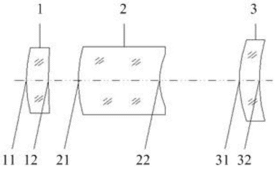
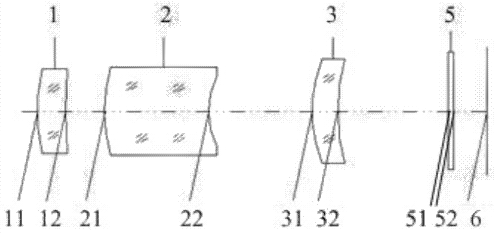
[0037] This embodiment is an imaging lens for close-range monocular iris recognition, such as figure 2 As shown, it is composed of three lens groups and a flat filter 5, and the rear of the imaging lens is provided with picture Image sensor 6, along the incident direction of light is followed by: plane filter 5; the first lens 1 with positive power, which is a convex-concave lens, the front surface 11 is a convex surface, and the rear surface 12 is a concave surface; The second lens 2 is a convex-concave lens, the front surface 21 is a convex surface, and the rear surface 22 is a concave surface; the third lens 3 with positive refractive power is a convex-concave lens, and the front surface 31 is a convex surface, and the rear surface 32 is a concave surface; The lens and flat filter are made of glass; the imaging surface is picture Like the sensor face, which is a CCD or CMOS sensor.

[0038] The imaging lens of this embodiment has an imaging wavelength of 700-900nm in the...

Embodiment 2

[0044] This embodiment is an imaging lens for monocular iris recognition, such as Figure 4 As shown, it is composed of three lens groups and a diaphragm 4, and the rear of the imaging lens is provided with picture Image sensor 6, along the incident direction of light, is: the first lens 1 with positive refractive power, which is a convex-concave lens, the front surface 11 is a convex surface, and the rear surface 12 is a concave surface; the second lens 2 with negative refractive power, which It is a convex-concave lens, the front surface 21 is a convex surface, and the rear surface 22 is a concave surface; the third lens 3 with positive refractive power is a convex-concave lens, the front surface 31 is a convex surface, and the rear surface 32 is a concave surface; the diaphragm 4 is located at the first lens Between 1 and the second lens 2, the three lenses are made of glass; the imaging surface is picture Like the sensor face, which is a CCD or CMOS sensor.

[0045] The ...


PUM


Abstract

The invention discloses an imaging lens, an iris imaging module and an iris identification device, and belongs to the field of biological identification. From front to back of a light incidence direction, the imaging lens sequentially comprises: a first lens, wherein the first lens is a convex-concave lens with positive power, the front surface is a convex surface, and the back surface is a concave surface; a second lens, wherein the second lens is a convex-concave lens with negative power, the front surface is a convex surface, and the back surface is a concave surface; and a third lens, wherein the third is a convex-concave lens with positive power, the front surface is a convex surface, and the back surface is a concave surface. The imaging lens provided by the invention is good in imaging quality, simple in structure and low in cost.

Description

technical field [0001] The invention relates to the field of biological identification, in particular to an imaging lens, an iris imaging module and an iris identification device. Background technique [0002] Iris recognition belongs to the field of biometrics. It is a biometric technology based on the iris of the eye. This technology authenticates the user's identity by processing the iris texture information in an area smaller than 10mm. Compared with other biometric technologies, iris recognition is unique and stable. It has become the most accurate identification technology at present. The difficulty in realizing iris recognition technology lies in how to collect clear and high-quality irises picture like, thus collecting the iris picture The optical system of the image becomes the key of the iris recognition device. [0003] The existing iris collection optical system can be divided into: zoom optical system and fixed focus optical system, among which the zoom optic...

Claims


Application Information

Patent Timeline
IPC IPC(8): G02B13/00G06K9/00
Inventor 马淑媛
Owner 深圳眼神智能科技有限公司
Why Eureka
Try Eureka