Optical path adjusting device and method

A technology for adjusting the device and optical path, which is applied in the field of photolithography and can solve the problems of low contrast of alignment signals

Active Publication Date: 2016-03-30
SHANGHAI MICRO ELECTRONICS EQUIP (GRP) CO LTD
View PDF12 Cites 7 Cited by
  • Summary
  • Abstract
  • Description
  • Claims
  • Application Information

AI Technical Summary

Problems solved by technology

[0009] The object of the present invention is to provide an optical path adjustment device and an optical path adjustment method to

Method used


Image

  • Optical path adjusting device and method
  • Optical path adjusting device and method
  • Optical path adjusting device and method

Examples


Embodiment Construction

[0029] The optical distance adjustment device and the optical distance adjustment method proposed by the present invention will be further described in detail below in conjunction with the accompanying drawings and specific embodiments. Advantages and features of the present invention will be apparent from the following description and claims. It should be noted that all the drawings are in a very simplified form and use imprecise scales, and are only used to facilitate and clearly assist the purpose of illustrating the embodiments of the present invention.

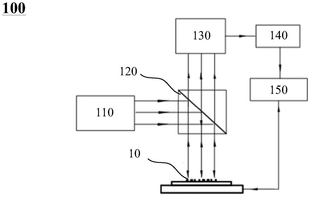
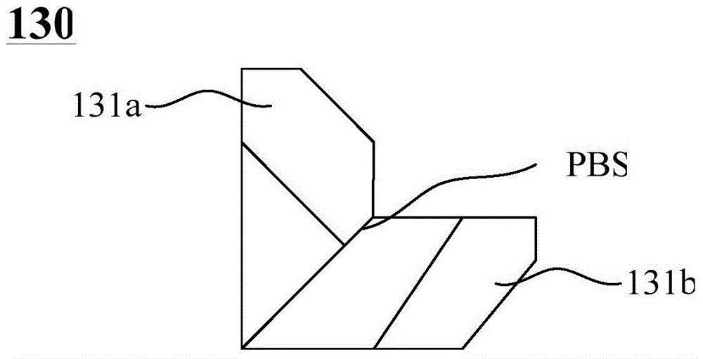
[0030] The contrast of the existing self-referencing interferometric alignment system is low, which affects the alignment accuracy of the self-referencing interferometric alignment system 100 . The inventor has conducted in-depth research on this and found that the reason for the low contrast of the existing self-referencing interferometric alignment system is that the self-referencing interferometer of the existing self-...


PUM


Abstract

The invention provides an optical path adjusting device and method. The optical path adjusting device adjusts the relative position of a first prism and a second prism in a self-reference interferometer so as to accurately adjust an optical path, and prevents a self-reference interference aligning system using the self-reference interferometer from generating zero-order light leakage due to a combined error of the first prism and the second prism so as to further increase the contrast of an aligning signal.

Description

technical field [0001] The invention relates to the technical field of photolithography, in particular to an optical path adjustment device and an optical path adjustment method. Background technique [0002] Photolithography is the process of transferring the graphic structure on the mask to the surface of the substrate coated with photoresist (PR) through exposure, development and other steps. In order to ensure that the graphics are correctly transferred to the substrate Precise alignment of the reticle to the substrate at the target location is important. Especially the manufacturing process that needs to go through multiple photolithography processes, such as the chip manufacturing process. In the chip manufacturing process, it is necessary to perform multiple photolithography processes on the silicon wafer. During each photolithography process, it is necessary to ensure the correct relative position between the pattern formed by this photolithography and the pattern f...

Claims


Application Information

Patent Timeline
IPC IPC(8): G02B27/00G03F7/20
Inventor 蓝科李运锋宋海军忻斌杰王诗华
Owner SHANGHAI MICRO ELECTRONICS EQUIP (GRP) CO LTD
Why Eureka
Try Eureka