
Smart home control system

A smart home control and main control module technology, applied in general control system, control/regulation system, program control, etc., can solve the problems of smart home control system performance discount, air switch easy to catch fire, arc generation, etc., to achieve display Intuitive, long-lasting and easy-to-install effects

Active Publication Date: 2016-03-30
沈德稳
View PDF7 Cites 3 Cited by
  • Summary
  • Abstract
  • Description
  • Claims
  • Application Information

AI Technical Summary

Problems solved by technology

However, there are certain problems in the installation of smart home control systems at present.
For example, if you install a smart home control system after the house decoration has been completed, there will be troubles in wiring, which will greatly reduce the performance of the smart home control system.
[0003] At present, the air switch with mechanical connection is installed in the concealed assembly electrical box or air switch box. Since the air switch is in mechanical contact, the air switch is easy to catch fire and generate an arc when it is turned on.
When there is a leak of flammable gas in the room, the opening and closing of the air switch will bring unpredictable consequences

Method used


Image

  • Smart home control system
  • Smart home control system
  • Smart home control system

Examples


Embodiment Construction

[0021] The technical solutions of the present invention will be described in detail below in conjunction with the accompanying drawings and embodiments.

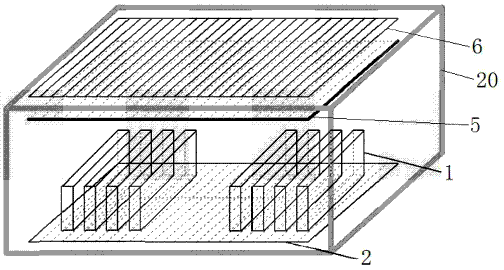
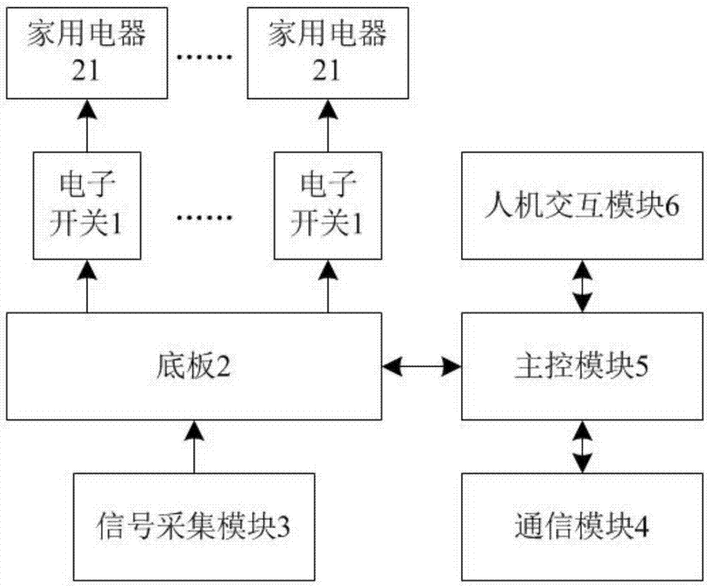
[0022] Such as figure 1 and figure 2 As shown, the present invention provides a smart home control system, which includes at least one electronic switch 1 , a base plate 2 , a signal acquisition module 3 , a communication module 4 , a main control module 5 and a human-computer interaction module 6 . Among them, the electronic switch 1, the base plate 2, the signal acquisition module 3, the communication module 4 and the main control module 5 are all fixedly installed in the concealed assembly electric box or the air switch box 20, and the human-computer interaction module 6 is fixedly installed in the concealed assembly electrical box. The surface of the box or air switch box 20.

[0023] The household appliance 21 is connected to the base plate 2 through the electronic switch 1, the electronic switch 1 and the base plate...


PUM


Abstract

The invention provides a smart home control system. The smart home control system comprises at least one electronic switch, a motherboard, a signal acquisition module, a communication module, a main control module and a man-machine interaction module; household electric appliances are connected with the bottom plate through the electronic switches; the electronic switches are in pluggable connection with the bottom plate; the signal acquisition module is connected with the bottom plate; the bottom plate, the communication module and the human-machine interface module are respectively connected with the main control module; the signal acquisition module transmits acquired working voltage, working current, electric leakage current, and the temperature value signals of wires to the main control module through the bottom plate, so that the working voltage, working current, electric leakage current, and the temperature value signals of the wires can be processed; the main control module transmits the processed signals to the human-computer interaction module for displaying the signals, and transmits switching-on and switching-off signals to the electronic switches through the bottom plate; and the main control module communicates with an external intelligent terminal through the communication module. The smart home control system of the invention can be fixedly installed in a concealed installation power distribution box or an air switch box, and therefore, the smart home control system will not occupy additional space, and room wiring is not required to be changed. The smart home control system has the advantages of simple installation, intuitive display and convenient operation.

Description

technical field [0001] The invention belongs to the technical field of home appliances, and in particular relates to a smart home control system. Background technique [0002] With the development of electronic technology, people's requirements for material living standards are getting higher and higher, and the requirements for living environment are also getting higher and higher. In recent years, various smart home control systems have appeared on the market, and their functions are becoming more and more perfect. Therefore, smart home control systems are more and more used in people's family life. However, there are certain problems with the installation of smart home control systems at present. For example, if the smart home control system is installed after the house decoration has been completed, there will be troubles in wiring, so that the performance of the smart home control system will be greatly reduced. [0003] At present, the air switch with mechanical conn...

Claims


Application Information

Patent Timeline
IPC IPC(8): G05B15/02G05B19/418
CPCG05B15/02G05B19/418G05B2219/2642
Inventor 沈德稳
Owner 沈德稳
Learn More