Microwave cavity stability optimization method independent of circuit and miniaturization microwave assembly obtained based on the same
A microwave cavity and optimization method technology, applied in the field of radio frequency microwave, can solve problems affecting circuit design, circuit layout changes, restrictions, etc., to achieve the effects of optimizing performance, convenient and flexible use, and improving component stability
- Summary
- Abstract
- Description
- Claims
- Application Information
AI Technical Summary
Problems solved by technology
Method used
Image
Examples
Embodiment 1
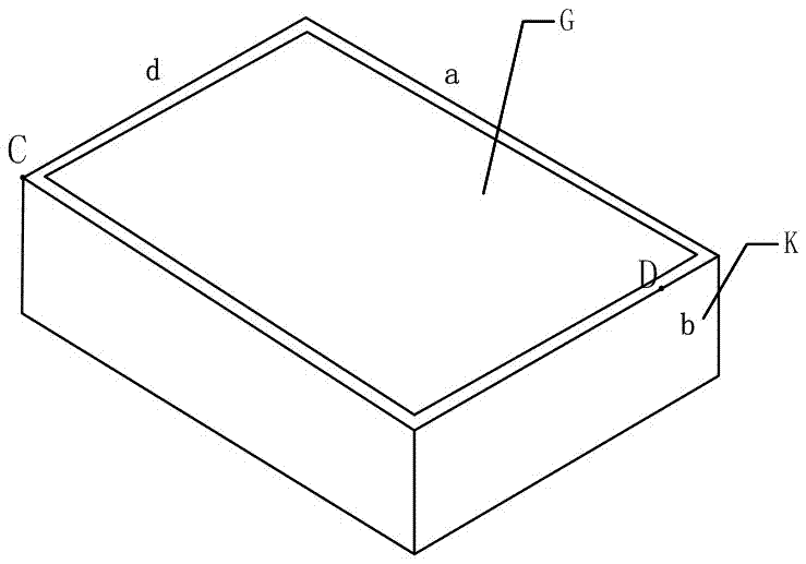
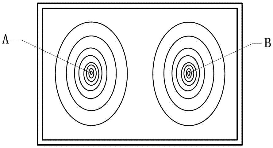
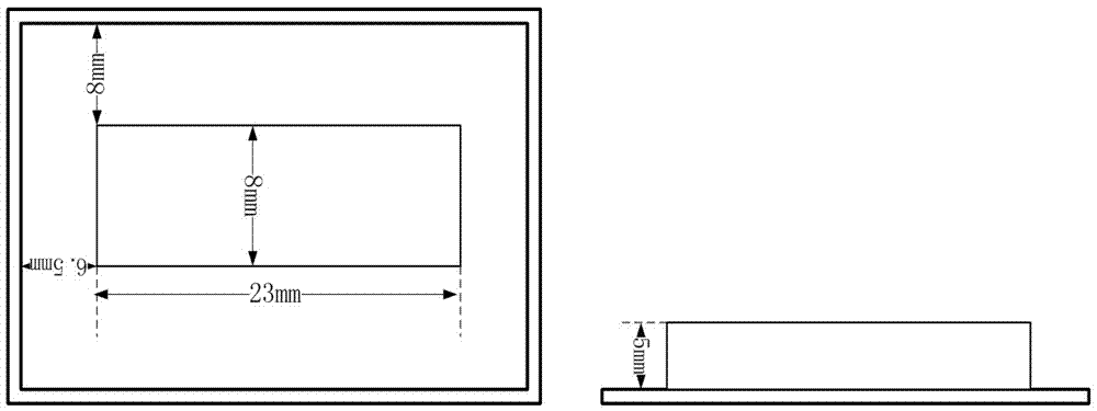
[0068] see image 3 Furthermore, a rectangular boss 3 is provided under the cover plate 2. The planar size of the boss 3 is 23mm*8mm, and the thickness is 5mm. The distance between them is 8mm, and the distance between 6.5mm and 6.5mm is greater than 0.1mm. The distance between the boss 3 and the bottom surface of the cavity is 3 mm, ensuring that the distance between the bottom surface of the boss 3 and the top surface of the components in the box body 1 is not less than 0.1 mm. The boss is placed for the purpose of destroying figure 2 The field distribution of the resonant mode shown.
[0069] will have image 3 The shown rectangular microwave cavity of the boss 3 cover is modeled and simulated in HFSS to obtain its resonance mode. The simulation results show that the resonant frequency points are all outside the working frequency band, and the closest resonant points to the working frequency band are f=12.17GHz and f=7.95GHz, which ensures that there is no resonant mod...
Embodiment 2
[0077] see Figure 7 , further speaking, two longitudinally parallel square bosses 3 are provided under the cover plate 2 . The size of the boss 3 is 6mm*6mm, and the thickness is 8mm. As shown in the figure, the distance between the side of each boss 3 and the inner wall of the adjacent box body 1 is not less than 0.1mm. The distance between the bottom surface of the boss 3 and the top surface of the components in the box body 1 is not less than 0.1 mm. The distance between the bosses 3 is not less than 0.1mm. The microwave cavity with the cover plate of this structure is modeled and simulated in HFSS, and the resonance points closest to the working frequency band can be obtained as f=13.35GHz and f=8.69GHz. Because the increase of the boss changes the effective values of a, b, and d, which destroys the field distribution inside the cavity, and there is no resonance frequency point in the X-band range.
[0078] see Figure 8 ,Will Figure 7The thickness of the upper bo...
Embodiment 3
[0084] see Figure 13 , further speaking, three bosses 3 are provided under the cover plate 2 . Two cylindrical bosses with a diameter of 3mm and a thickness of 7mm and a rectangular boss of 10mm*5.5mm and a thickness of 7mm. The position of the boss is as Figure 13 As shown, the distance between the side of each boss 3 and the inner wall of the adjacent box body 1 is not less than 0.1 mm. The distance between the bottom surface of the boss 3 and the top surface of the components in the box body 1 is not less than 0.1mm. The distance between the bosses 3 is not less than 0.1mm.
[0085] The microwave cavity with the cover plate of this structure is modeled and simulated in HFSS, and the resonance points closest to the working frequency band are f=12.38GHz and f=6.7GHz, and there is no resonance point in the working frequency band, which achieves the expected effect.
PUM
 Abstract
Description
Claims
Application Information
 - R&D
- Intellectual Property
- Life Sciences
- Materials
- Tech Scout
- Unparalleled Data Quality
- Higher Quality Content
- 60% Fewer Hallucinations
Browse by: Latest US Patents, China's latest patents, Technical Efficacy Thesaurus, Application Domain, Technology Topic, Popular Technical Reports.
© 2025 PatSnap. All rights reserved.Legal|Privacy policy|Modern Slavery Act Transparency Statement|Sitemap|About US| Contact US: help@patsnap.com


