Generalized state space averaging modeling method for aviation 12-pulse inverter
A technology of state space averaging and modeling method, applied in electrical engineering, aerospace field, can solve the problems of inappropriate analysis of large-signal disturbance of airborne inverter, dynamic analysis that cannot meet fast change and large-signal disturbance, etc. The effect of increased accuracy, reduced maintenance costs, increased precision and speed
- Summary
- Abstract
- Description
- Claims
- Application Information
AI Technical Summary
Problems solved by technology
Method used
Image
Examples
Embodiment 1
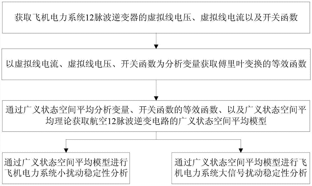
[0038] A generalized state-space average modeling method for aviation 12-pulse inverters, see figure 2 , the generalized state-space average modeling method includes the following steps:
[0039] 101: Obtain the virtual line voltage, virtual line current and switching function of the 12-pulse inverter in the aircraft power system;
[0040] 102: Take the virtual line current and virtual line voltage as the analysis variables to obtain the generalized state space average analysis variables, and at the same time obtain the equivalent function of the switching function;
[0041] 103: Obtain the generalized state space average model of the aviation 12-pulse inverter circuit through the generalized state space average analysis variables, the equivalent function of the switching function, and the generalized state space average theory.
[0042] Wherein, the switching function in step 101 is:
[0043] the s ui = 1, s ui =0 represents the turn-on and turn-off of the upper bridge a...
Embodiment 2
[0055] 201: Obtain the virtual line voltage, virtual line current and switching function of the 12-pulse inverter of the aircraft power system;
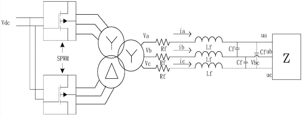
[0056] see image 3 , the 12-pulse inverter analysis topology of the aircraft power system adopts image 3 The structure shown (this structure is well known to those skilled in the art), the circuit is composed of two three-phase bridge inverter circuits, the input DC source is a public DC power supply, and the output voltage is connected in parallel through a transformer. The transformer adopts the Y and △ connection method, and the voltage difference between the upper and lower beam bridges is 30 degrees to form a 12-pulse inverter circuit. Because the fundamental wave differs by 30 electrical degrees, and the corresponding 6th harmonic differs by 180 electrical angles to cancel each other out, and the output voltage and current do not contain 6th harmonics. For a three-phase PWM inverter circuit modulated by a sine wave, when th...
Embodiment 3
[0092] Below in conjunction with concrete experimental data, the scheme in embodiment 1 and 2 is carried out feasibility verification, see the following description for details:
[0093] Determine the analysis parameters of the inverter circuit of the aircraft power system;
[0094] with V ab and I ab For the analysis object, select the parameters of the inverter circuit as shown in Table 1
[0095] Table 1 inverter circuit parameters
[0096]
[0097] According to the size of each variable in Table 1, the large disturbance analysis of the inverter circuit is carried out. During the analysis, the large signal disturbance received by the inverter circuit is equivalent to the change of the load impedance.
[0098] Using SPWM inverter circuit, connected to the load resistance 80Ω, the signal and the voltage waveform of the secondary side of the transformer are as follows: Figure 4 shown.
[0099] Assuming that a large disturbance occurs at 10ms, the l...
PUM
 Abstract
Description
Claims
Application Information
 - R&D
- Intellectual Property
- Life Sciences
- Materials
- Tech Scout
- Unparalleled Data Quality
- Higher Quality Content
- 60% Fewer Hallucinations
Browse by: Latest US Patents, China's latest patents, Technical Efficacy Thesaurus, Application Domain, Technology Topic, Popular Technical Reports.
© 2025 PatSnap. All rights reserved.Legal|Privacy policy|Modern Slavery Act Transparency Statement|Sitemap|About US| Contact US: help@patsnap.com


