Switching inductance equalization controller and control method for energy storage device

A technology of switching inductors and energy storage devices, which is applied to current collectors, circuit devices, charge equalization circuits, etc., can solve the problems of slow speed, non-energy storage and voltage equalization method system complexity, etc., to avoid reciprocating flow and speed up equalization The effect of circuit speed and high efficiency

Active Publication Date: 2017-11-03
严格集团股份有限公司
View PDF3 Cites 0 Cited by
  • Summary
  • Abstract
  • Description
  • Claims
  • Application Information

AI Technical Summary

Problems solved by technology

[0004] The purpose of the present invention is to solve the problem that the existing energy-consuming energy storage and equalization method is slow and the non-energy-consuming energy storage and equalization method is complicated, and proposes a switch inductor voltage equalization controller and control for energy storage devices. method

Method used


Image

  • Switching inductance equalization controller and control method for energy storage device
  • Switching inductance equalization controller and control method for energy storage device
  • Switching inductance equalization controller and control method for energy storage device

Examples


specific Embodiment approach 1

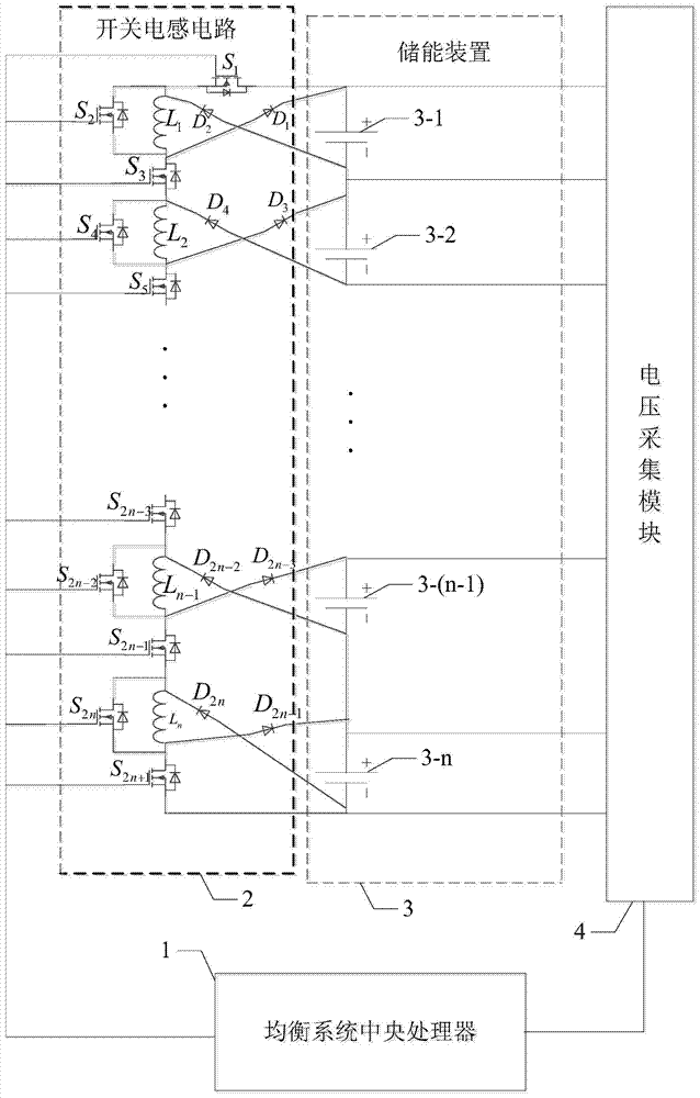
[0046] Specific implementation mode one: combine Figure 1-Figure 3 Describe this embodiment, the switch inductor voltage equalization controller for energy storage device described in this embodiment, it comprises balance system CPU 1, switch inductor circuit 2 and voltage acquisition module 4;

[0047] The energy storage device 3 includes n energy storage units, and the n energy storage units are connected in series; the n is a positive integer, and n≥2;

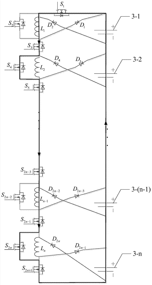
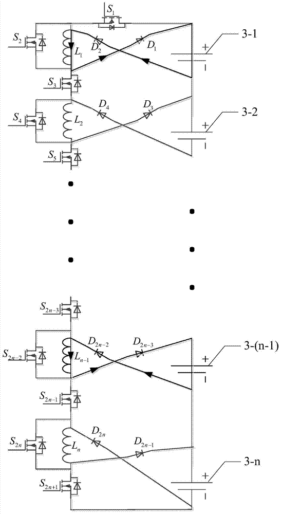
[0048] The switch inductor circuit 2 includes 2n diodes, n energy storage inductors and 2n+1 switch tubes;

[0049] The anodes of the first energy storage unit 3-1, the second energy storage unit 3-2 to the nth energy storage unit 3-n are respectively connected to the first diode D in turn. 1 , the third diode D 3 to the 2n-1th diode D 2n-1 connected to the cathode of the first diode D 1 , the third diode D 3 to the 2n-1th diode D 2n-1 The anode of the first inductance L in turn respectively 1 , the second inductanc...

specific Embodiment approach 2

[0072] Embodiment 2: This embodiment is a further description of the switching inductor voltage equalization controller for energy storage devices described in Embodiment 1. In this embodiment, the unit that sends the periodic shutdown signal can also control all the switching tubes , causing it to enter the shutdown state.

specific Embodiment approach 3

[0073] Specific implementation mode three: combination Figure 4 Describe this embodiment, the control method of the switching inductor voltage equalizing controller for the energy storage device described in this embodiment, the method is realized based on the switching inductor voltage equalizing controller of the energy storage device, the energy storage device The switch inductor voltage equalization controller includes an equalization system CPU 1, a switch inductor circuit 2 and a voltage acquisition module;

[0074] The energy storage device 3 includes n energy storage units, and the n energy storage units are connected in series;

[0075] The switch inductor circuit 2 includes 2n diodes, n energy storage inductors and 2n+1 switch tubes;

[0076] The anodes of the first energy storage unit 3-1, the second energy storage unit 3-2 to the nth energy storage unit 3-n are respectively connected to the first diode D in turn. 1 , the third diode D 3 to the 2n-1th diode D 2...


PUM


Abstract

A switch inductance voltage equalizing controller and control method for an energy storage device relates to the voltage equalizing control technique of the energy storage device, solving the problem that the current energy consumption storage voltage equalizing method is slow in speed and the non-energy consumption storage voltage equalizing method is complex in system. The voltage collecting unit of the invention is used for collecting the voltages of n energy storage units and sends the voltage signals of the n energy storage units; an equalizing system central processing unit is used for receiving the voltage signals of the n energy storage units, calculating the average voltage value of the n energy storage units, judging the high / low relationship of the voltage value of every n energy storage unit and the average voltage value of the n energy storage units, generates a control signal according to the judging result and sends periodic signals; a switch inductance circuit is used for receiving the control signal and the periodic signals; the n is positive integer, and n is more than or equal to 2. The invention is advantaged by wide suitable application, high voltage equalizing efficiency, rapid voltage equalizing speed and suitability of equalizing the voltage of the energy storage device.

Description

technical field [0001] The invention relates to the pressure equalization control technology of an energy storage device. Background technique [0002] In new energy fields such as wind power, photovoltaic-based distributed power generation, and micro-grid construction, the power support technology is proposed for the instantaneous power balance between power generation and power consumption. In the actual operation of the microgrid, an energy storage system is required to dynamically adjust the instantaneous power to meet the instantaneous power balance between supply, demand and storage. Only when the instantaneous power is balanced and adjusted can the microgrid system operate stably. The commonly used electric energy storage methods include supercapacitor technology, lithium battery technology, lead-acid battery technology, etc., and the terminal voltage of these energy storage units is relatively low and needs to be used in series. [0003] In the process of series us...

Claims


Application Information

Patent Timeline
Patent Type & Authority Patents(China)
IPC IPC(8): H02J7/00
CPCH02J7/0019H02J7/345
Inventor 段建东凡绍桂孙力肖倩刘云霞
Owner 严格集团股份有限公司
Why Eureka
Try Eureka