Difference PWM modulator and current-mode DC-DC converter based on the modulator

A modulator and current mode technology, which is used in output power conversion devices, regulating electrical variables, converting DC power input to DC power output, etc. DCDC converter and other problems, to achieve the effects of easy stability design, wide current range, common mode voltage generation and slope compensation functions

Inactive Publication Date: 2016-03-30
SHANGHAI SOVAN ELECTRONICS TECH CO LTD
View PDF9 Cites 2 Cited by
  • Summary
  • Abstract
  • Description
  • Claims
  • Application Information

AI Technical Summary

Problems solved by technology

[0006] The purpose of the present invention is to solve the problem that traditional single-ended modulators are not suitable for current-mode DCDC converters that use off-chip resistors to detect output currents. The present invention provides a differential PWM modulator and current-mode DCDC conversion based on the modulator device

Method used


Image

  • Difference PWM modulator and current-mode DC-DC converter based on the modulator
  • Difference PWM modulator and current-mode DC-DC converter based on the modulator
  • Difference PWM modulator and current-mode DC-DC converter based on the modulator

Examples


Embodiment Construction

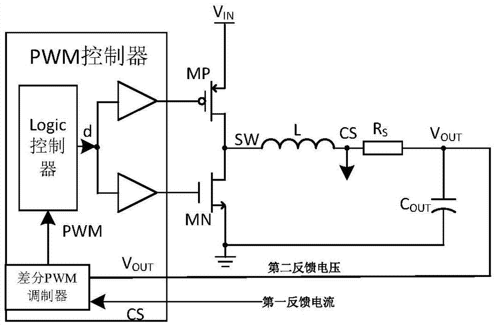
[0038] This embodiment is specifically a current mode DCDC converter, such as image 3 As shown, including differential PWM modulator, logic controller, two buffers, NOT gate, NMOS tube MN, PMOS tube MP, inductor L, electrolytic capacitor C OUT and resistor R S ;

[0039]The output of the differential PWM modulator is input to the logic controller, the logic controller outputs a square wave signal d, the square wave signal d passes through the first buffer and is input to the gate of the PMOS transistor MP through the NOT gate, and the square wave signal d passes through the second The buffer is input to the gate of the NMOS transistor MN, the drain of the PMOS transistor MP and the drain of the NMOS transistor MN are connected to one end of the inductor L at the same time, and the other end of the inductor L is connected to the resistor R S Connected at one end, the resistor R S The other end of the electrolytic capacitor C OUT The positive connection of the electrolytic ...


PUM


Abstract

The invention discloses a difference PWM modulator and a current-mode DC-DC converter based on the modulator, for solving the problem that a conventional single-end modulator is not suitable for a current-mode DC-DC converter which detects output currents by use of an off-chip resistor. The difference PWM modulator comprises: difference-mode voltages between single-end control voltages and common-mode voltages are amplified through a gain grade A1, difference voltages of feedback currents are amplified through a gain grade A2, after amplification through the gain grade A1 and the gain grade A2, difference signals are input to a comparator for comparison, PWM output is generated, and differences between first feedback voltages CS and second feedback voltages VOUT are the difference voltages of the feedback currents. According to the invention, a detection resistor RS of the current-mode DC-DC converter based on the modulator is arranged in an output path, and peak or valley current-mode PWM is realized by use of the difference voltages on the resistor RS. The difference PWM modulator is suitable for application of a battery charger and the like which need off-chip resistors for detecting output currents.

Description

technical field [0001] The invention relates to a PWM modulator and a current-mode DC-DC converter based on the modulator. Background technique [0002] The DC-DC converter composed of PWM controller chip combined with discrete MOSFET switches has the advantages of strong current capability and high reliability. However, since there is no current feedback path, this type of DCDC mostly adopts voltage mode control, that is, only feeds back the DCDC output voltage, such as figure 1 , its disadvantages are poorer load regulation than current mode, and a more complex compensation network required for voltage mode control. [0003] It is also possible to add a resistor R at the MN source end of the lower tube S ,Such as figure 2 , to introduce current feedback to realize current limiting or current mode control. However, it only detects the current of one phase in the PWM cycle, and cannot accurately reflect the magnitude of the output current. [0004] In applications such...

Claims


Application Information

Patent Timeline
Patent Type & Authority Applications(China)
IPC IPC(8): H02M3/156
CPCH02M3/156H02M1/0025
Inventor 乐忠明
Owner SHANGHAI SOVAN ELECTRONICS TECH CO LTD
Why Eureka
Try Eureka