Wrist of robot and surgical robot

A robot and wrist technology, applied in the field of robot wrists and surgical robots, can solve problems such as difficult control, low control precision of wrist joints, and small rotation range

Active Publication Date: 2016-04-06
SHANGHAI MICROPORT MEDBOT (GRP) CO LTD
View PDF6 Cites 20 Cited by
  • Summary
  • Abstract
  • Description
  • Claims
  • Application Information

AI Technical Summary

Problems solved by technology

[0009] The purpose of the present invention is to provide a robot wrist and a surgical robot to solve one or more of

Method used


Image

  • Wrist of robot and surgical robot
  • Wrist of robot and surgical robot
  • Wrist of robot and surgical robot

Examples


Embodiment 1

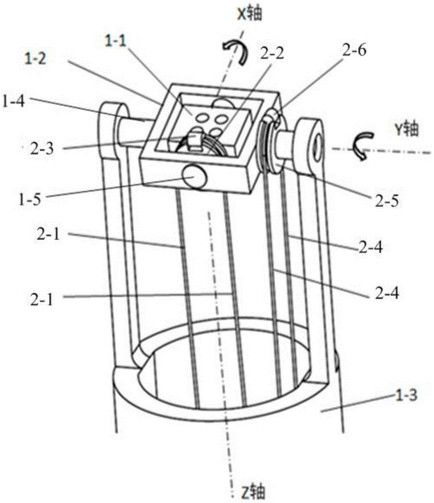
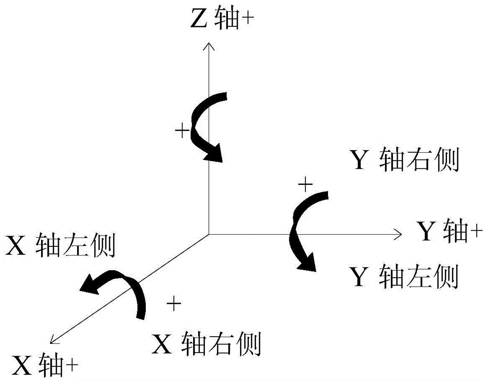
[0070] figure 1 It is a schematic diagram of the robot wrist in Embodiment 1 of the present invention, figure 2 for figure 1 The coordinate system of the robot wrist is shown.

[0071] refer to Figure 1~2, a robot wrist, comprising an inner rotating frame 1-1, an outer rotating frame 1-2, a base 1-3, a first rotating shaft 1-4 and a second rotating shaft 1-5, wherein the inner rotating frame 1- 1 is located inside the outer rotating frame 1-2, the outer rotating frame 1-2 is fixed on the first rotating shaft 1-4, and the two ends of the first rotating shaft 1-4 are respectively rotatably mounted on the base 1- 3, and the outer rotating frame 1-2 can rotate together with the first rotating shaft 1-4, while the inner rotating frame 1-1 is fixed on the second rotating shaft 1-5, the second rotating shaft The two ends of 1-5 are respectively rotatably installed in the shaft holes of the outer swivel frame 1-2, and the inner swivel frame 1-1 can rotate together with the secon...

Embodiment 2

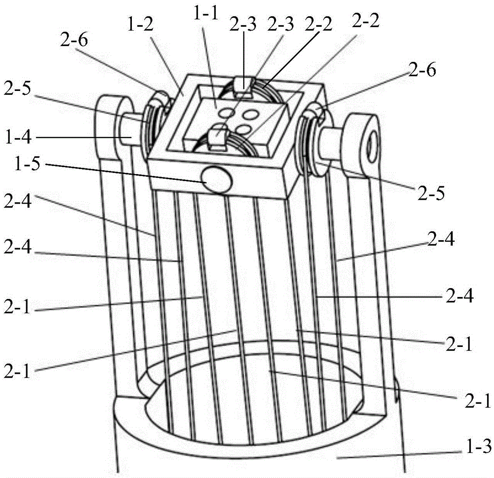
[0092] The difference between the second embodiment and the first embodiment is that the number of the first driving wheel 2-2 and the second driving wheel 2-5 are respectively increased from one to two, and the two first driving wheels 2-2 are sleeved It is fixedly connected with the inner rotating frame 1-1 on the second rotating shaft 1-5, and two first driving wheels 2-2 are arranged symmetrically on the left and right sides of the inner rotating frame 1-1 (ie, the Y axis). Similarly, the two second driving wheels 2-5 are sleeved on the first rotating shaft 1-4 and fixedly connected with the outer rotating frame 1-2, and the two second driving wheels 2-5 are symmetrically arranged on the outer rotating frame 1-2. 2 (that is, the left and right sides of the X-axis), see for details image 3 .

[0093] Such as image 3 As shown, the first transmission mechanism includes two first driving ropes 2-1 and two first driving wheels 2-2, and the two first driving wheels 2-2 are bot...

Embodiment 3

[0099] The difference between the third embodiment and the first embodiment is that the first driving rope 2-1 and the first driving wheel 2-2 are replaced by two driving ropes, and the two driving ropes are respectively arranged at the ends of the second rotating shaft 1-5. left and right, to drive the inner rotating frame 1-1 to rotate positively or reversely around the X axis through the two driving ropes, see for details Figure 4 .

[0100] Such as Figure 4 As shown, the first transmission mechanism includes a third driving rope 2-7 and a fourth driving rope 2-8, and one end of the third driving rope 2-7 is fixed on the inner rotating frame 1-1 And arranged on the left side of the X-axis, the other end of the third driving rope 2-7 passes through the through hole in the central part of the base 1-3 and is connected to a motor; correspondingly, the fourth driving rope 2-8 One end of which is fixed on the inner rotating frame 1-1 and is arranged on the right side of the ...


PUM


Abstract

The invention provides a wrist of a robot and the surgical robot. The wrist of the robot comprises a substrate, a hooke joint structure, a first transmission mechanism, a second transmission mechanism and a driving mechanism. The hooke joint structure is arranged on the substrate, and used for fixing a surgical instrument. The driving mechanism drives the first transmission mechanism and the second transmission mechanism to move, and the first transmission mechanism and the second transmission mechanism drive the hooke joint structure to rotate at the first freedom degree and the second freedom degree respectively. At least one of the first transmission mechanism and the second transmission mechanism is a linear transmission mechanism and used for linearly driving the hooke joint structure to move. The rotation of each freedom degree is independently controlled to be driven by the first transmission mechanism and the second transmission mechanism. At least one of the first transmission mechanism and the second transmission mechanism is the linear transmission mechanism and used for linearly driving the hooke joint structure to move. Due to the fact that linear driving can be precisely controlled, control precision is high.

Description

technical field [0001] The invention relates to the technical field of medical instruments, in particular to a robot wrist and a surgical robot. Background technique [0002] Laparoscopic surgery is a major advancement in the history of medicine. It refers to a minimally invasive abdominal surgery performed by doctors making a small incision of about 1 cm in the patient's abdomen, inserting long and thin surgical instruments through the incision, and performing laparoscopic monitoring. Because laparoscopic surgery can improve the previous open surgery problems such as large trauma, heavy bleeding, slow postoperative recovery, and obvious scars, it has been widely used in many surgical fields such as urology, cardiac surgery, and obstetrics and gynecology. However, traditional laparoscopic surgery uses less freedom of surgical instruments and fewer surgical actions, which greatly reduces the flexibility of surgical operations and makes it impossible to apply this technology t...

Claims


Application Information

Patent Timeline
IPC IPC(8): A61B34/30
Inventor 何超张骞王常春
Owner SHANGHAI MICROPORT MEDBOT (GRP) CO LTD
Why Eureka
Try Eureka