Tool used for track welding
A track welding and tooling technology, which is applied to tracks, welding equipment, auxiliary welding equipment, etc., to achieve the effects of high welding efficiency, convenient production, and simple operation
- Summary
- Abstract
- Description
- Claims
- Application Information
AI Technical Summary
Problems solved by technology
Method used
Image

Examples
Embodiment Construction
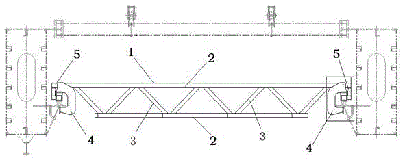
[0019] see figure 1 , a tooling for rail welding, including an inverted trapezoidal main hanger 1, a number of reinforcing ribs 3 are arranged between the upper and lower horizontal supports 2 of the main hanger 1, and the two ends of the main hanger 1 are horizontal along the upper The lower edge of the support 2 is provided with a jack base 4 and a running mechanism 5 in sequence. The connection between the reinforcing rib 3 and the horizontal support 2 is a 45-degree fillet weld, and the height of the welding angle is 0.7 times the thickness of the thin plate connected between the reinforcing rib 3 and the horizontal support 2 . An angle of 90 degrees is formed between two adjacent reinforcing ribs 3 . The upper and lower horizontal supports 2 and reinforcing ribs 3 of the main hang frame 1 are square tubes, the distance between two adjacent reinforcing ribs 3 is 60mm, and the main hang frame 1 adopts a square tube of 80×80mm. The main hang frame 1 is connected with the j...
PUM
 Abstract
Description
Claims
Application Information