Oil hydraulic press jacking device

A jacking device and hydraulic press technology, which is applied to presses, manufacturing tools, etc., can solve the problems of reducing the service life of hydraulic presses, declining working conditions of hydraulic presses, troublesome machine maintenance, etc., so as to avoid standstill, ensure normal work, and improve work efficiency Effect

Active Publication Date: 2016-04-06
江苏一重数控机床有限公司
View PDF4 Cites 0 Cited by
  • Summary
  • Abstract
  • Description
  • Claims
  • Application Information

AI Technical Summary

Problems solved by technology

[0002] The role of hydraulic presses in mechanical production is very important. They can often provide power sources for other mechanical equipment. Compared with other power devices, hydraulic presses save energy and have lower noise, which makes hydraulic presses more and more widely used. However, many The life of the hydraulic press is short when it is in use, and it is very troublesome to maintain the machine, especially on the jacking device. During the use of the hydraulic press, the track rollers need to be used frequently. Long-term rolling makes the track rollers very easy to damage. Replacement The frequency is high, which increases the use and maintenance cost of the hydraulic press. The rail roller is in a sealed state when it is in use. The long-term friction makes the temperature between the rail roller and the connecting piece very good, and the heat inside cannot be discharged, which is easy to form High-temperature working environment, such working environment makes the track roller become seriously carbonized, which is easy to cause the corrosion of the track roller, which reduces the working condition of the hydraulic press and reduces the service life of the hydraulic press

Method used


Image

  • Oil hydraulic press jacking device

Examples


Embodiment Construction

[0013] The present invention will be further described below in conjunction with the accompanying drawings.

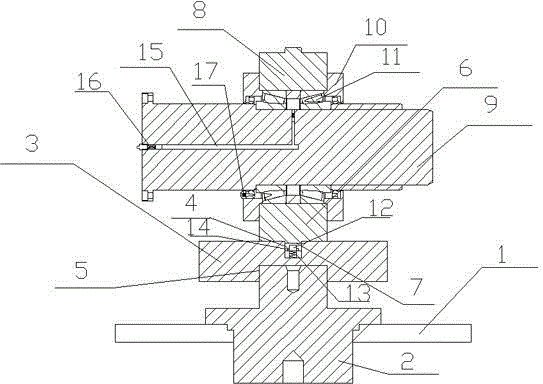
[0014] A jacking device for a hydraulic press, comprising a frame 1, a lifting cylinder 2 and a railed lifting plate 3, a lifting cylinder 2 is arranged in the middle of the frame 1, the bottom of the lifting cylinder 2 is located in the frame 1, and the top of the lifting cylinder 2 is a boss structure , the rail lifting plate 3 is strip-shaped, and the rail lifting plate 3 is provided with a groove, the groove is a double-sided groove, the width of the upper groove 4 is less than the width of the lower groove 5, and the upper groove 4 and the roller The belts 6 are connected to each other, and the roller belt 6 is provided with a protruding connector 7, and the protruding connector 7 is embedded in the upper groove, and the upper part of the upper groove 4 is provided with a rail roller 8, and the rail roller 8 is a circular roller. Rail roller assembly mechanism 9 i...


PUM


Abstract

Disclosed is an oil hydraulic press jacking device. The oil hydraulic press jacking device comprises a rack, a lifting cylinder and a tracked lifting plate. The lifting cylinder is arranged in the middle of the rack. The bottom of the lifting cylinder is located in the rack. The top of the lifting cylinder is of a boss structure. The tracked lifting plate is in a long strip shape and provided with a groove which is a two-side groove. The width of an upper groove body is smaller than that of a lower groove body. The upper groove body and a rolling wheel belt are mutually connected. The rolling wheel belt is provided with a convex connection part which is inlaid in the upper groove body. The upper portion of the upper groove body is provided with a tracked rolling wheel. Through the arrangement of the tracked lifting plate, the lifting function and the guide function can be achieved simultaneously, so that an oil hydraulic press works more stably. The tracked rolling wheel is fixed through an outer side clamping hoop, thereby being fixed more stably, and accordingly deviation is not liable to occur.

Description

technical field [0001] The invention relates to a jacking structure, in particular to a jacking device for a hydraulic press. Background technique [0002] The role of hydraulic presses in mechanical production is very important. They can often provide power sources for other mechanical equipment. Compared with other power devices, hydraulic presses save energy and have lower noise, which makes hydraulic presses more and more widely used. However, many The life of the hydraulic press is short when it is in use, and it is very troublesome to maintain the machine, especially on the jacking device. During the use of the hydraulic press, the track rollers need to be used frequently. Long-term rolling makes the track rollers very easy to damage. Replacement The frequency is high, which increases the use and maintenance cost of the hydraulic press. The rail roller is in a sealed state when it is in use. The long-term friction makes the temperature between the rail roller and the c...

Claims


Application Information

Patent Timeline
Patent Type & Authority Applications(China)
IPC IPC(8): B30B15/00B30B15/04
Inventor 王愉翔王修山刘凌
Owner 江苏一重数控机床有限公司
Why Eureka
Try Eureka