Washing flow divider

A diverter and diverter mechanism technology, applied in conveyors, rollers, transportation and packaging, etc., to achieve the effect of reducing input costs, increasing quantity, and reducing production costs

Inactive Publication Date: 2016-04-06
TIANJIN TTX GROUP
View PDF0 Cites 4 Cited by
  • Summary
  • Abstract
  • Description
  • Claims
  • Application Information

AI Technical Summary

Problems solved by technology

[0004] In view of this, the present invention aims to propose a cleaning diverter to solve the problem of achieving the diversion purpose with a simple structure and relatively strong versatility

Method used


Image

  • Washing flow divider
  • Washing flow divider

Examples


Embodiment Construction

[0027] It should be noted that, in the case of no conflict, the embodiments of the present invention and the features in the embodiments can be combined with each other.

[0028] In describing the present invention, it should be understood that the terms "center", "longitudinal", "transverse", "upper", "lower", "front", "rear", "left", "right", The orientations or positional relationships indicated by "vertical", "horizontal", "top", "bottom", "inner", "outer", etc. are based on the orientation or positional relationships shown in the drawings, and are only for the convenience of describing the present invention Creation and simplification of description, rather than indicating or implying that the device or element referred to must have a specific orientation, be constructed and operate in a specific orientation, and therefore should not be construed as limiting the invention. In addition, the terms "first", "second", etc. are used for descriptive purposes only, and should no...


PUM


Abstract

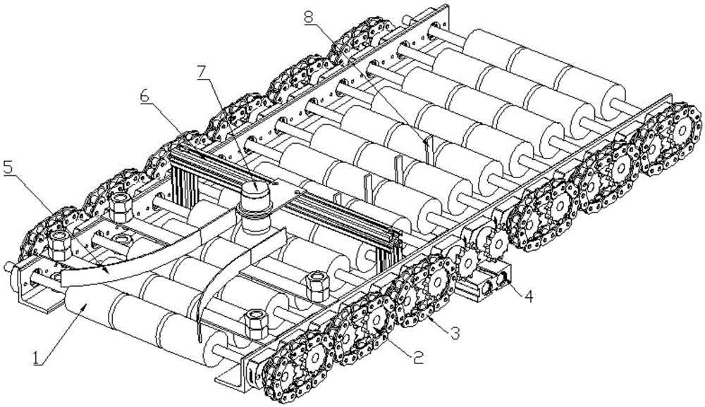
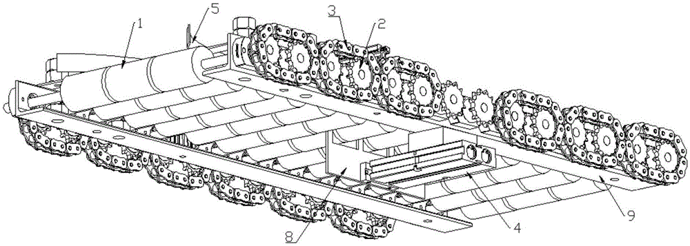
The invention provides a washing flow divider. The washing flow divider comprises a transmission mechanism and a flow dividing mechanism, wherein the transmission mechanism comprises a conveying assembly and a power assembly, the conveying assembly comprises a plurality of conveying rollers, the plurality of conveying rollers are arranged in parallel, the power assembly provides the conveying rollers with power rotating around respective axes, and the rotation of the plurality of conveying rollers in the same direction forms the conveying trajectory of the conveying assembly; and the flow dividing mechanism comprises a pushing power component, a shifting fork and a flow dividing guide vane positioned above the conveying rollers, the flow dividing guide vane is an arc-shaped sheet and is positioned at the tail of the conveying trajectory of the conveying assembly, the included angle between the tangent line of the flow dividing guide vane and the conveying trajectory of the conveying assembly is an acute angle, and the flow dividing guide vane is bent towards the side edge of the conveying trajectory. According to the invention, the purpose of dividing flow is achieved through the cooperation arrangement of the transmission mechanism and the flow dividing mechanism; and at the same time, as the flow dividing guide vane is used as the component for realizing flow dividing, the technology can reduce production cost. The washing flow divider is applied to the production of various products.

Description

technical field [0001] The invention belongs to the field of industrial processing and transportation, and in particular relates to a cleaning diverter. Background technique [0002] With the gradual increase of the scale of industrial production, many enterprises will basically divert and transport the workpiece after processing the workpiece to meet the requirements of the next process. However, the diversion device in this sense is often They are all designed for larger products, and smaller products often cannot use this shunt device due to their own limitations. [0003] In view of the above situation, manufacturers often design a separate device for shunting according to their own product characteristics, and this type of device not only has poor versatility, but also has high manufacturing costs, and the process is not particularly simple. Contents of the invention [0004] In view of this, the present invention aims to propose a cleaning diverter to solve the prob...

Claims


Application Information

Patent Timeline
Patent Type & Authority Applications(China)
IPC IPC(8): B65G13/00B65G21/00
CPCB65G13/00B65G21/00
Inventor 田捷才
Owner TIANJIN TTX GROUP
Why Eureka
Try Eureka