
Electroplating clamp for rubber plugs and electroplating method adopting same

A technology of electroplating fixtures and rubber plugs, which is applied in the electrolysis process and electrolytic components, etc. It can solve the problems affecting the quality of rubber plugs, injection molding rubber plugs, and the loss of electroplating layer wear and tear, and achieve the effect of strengthening the thickness

Active Publication Date: 2016-04-06
SHENGZHOU PHARMA PACKAGING MATERIALS TECH CHINA CO LTD
View PDF8 Cites 0 Cited by
  • Summary
  • Abstract
  • Description
  • Claims
  • Application Information

AI Technical Summary

Problems solved by technology

[0003] In the prior art, injection molding is generally used to produce this kind of rubber plug. The utility model patent with the application number "201020218053.8" discloses a chrome-plated rubber plug mold. It can be seen from its claims that in order to avoid the use of The release agent affects the hygienic index of the rubber stopper. The mold generally adopts the surface electroplating process method, and a layer of 0.5-1.5mm chrome plating is electroplated on the mold. However, in the electroplating process, the previous process generally uses the mold plate clamping, and then electroplating on the surface, but it can be seen from the structure of the rubber plug and background documents that the mold will have a cavity for the plug body to form, but in the electroplating process, the traditional process uses electrophoresis to The mold is electroplated, but the electroplating solution generally cannot flow in the cavity, so only a thin layer of electroplating film can be plated on the side wall of the cavity. Although the electroplating has been completed from the surface, after the mold has been used many times , its electroplating layer will be worn away, resulting in problems with the quality of injection plastic plugs

Method used


Image

  • Electroplating clamp for rubber plugs and electroplating method adopting same
  • Electroplating clamp for rubber plugs and electroplating method adopting same
  • Electroplating clamp for rubber plugs and electroplating method adopting same

Examples


Embodiment Construction

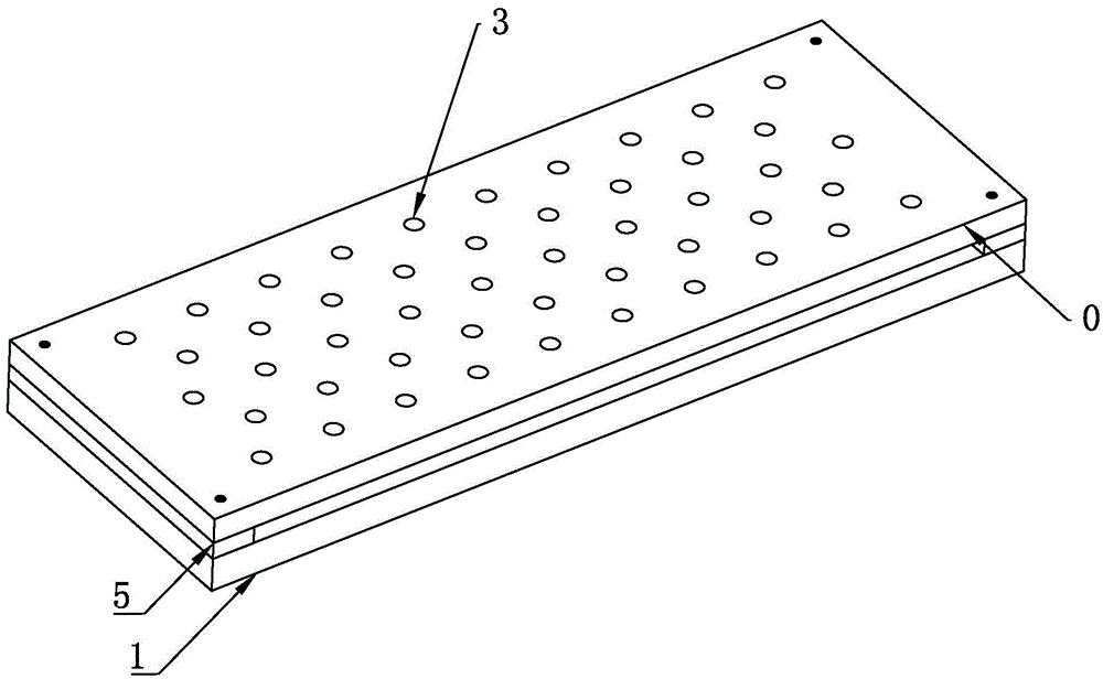
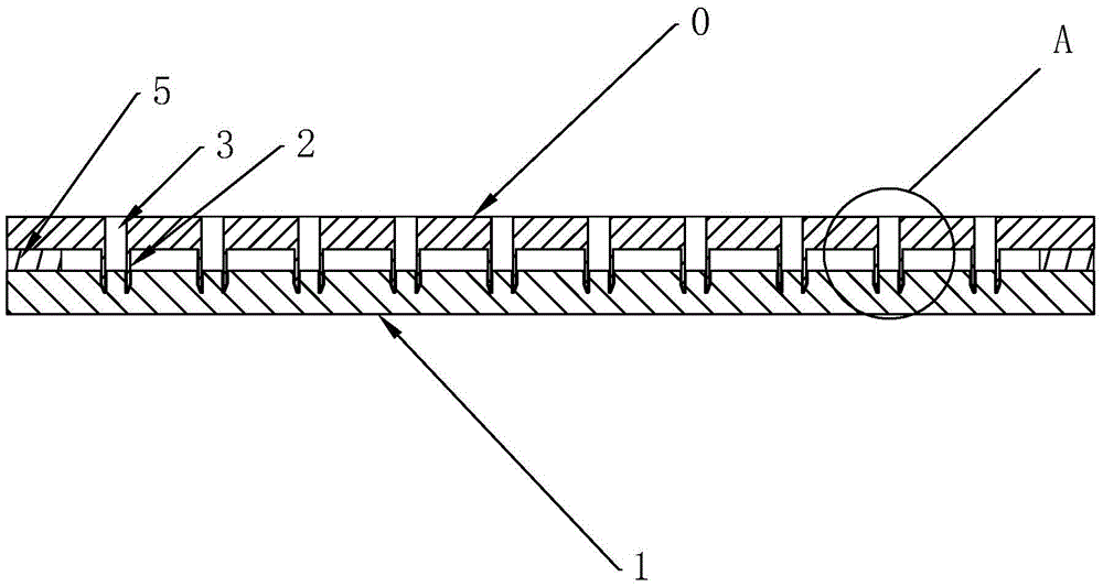
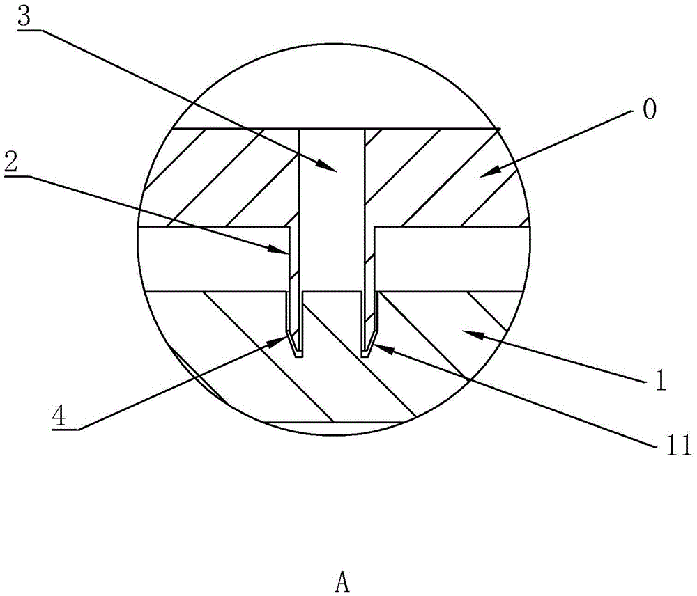
[0034] Attached to the following figure 1 to the attached image 3 The present invention will be described in further detail.

[0035] This specific embodiment is only an explanation of the present invention, and it is not a limitation of the present invention. Those skilled in the art can make modifications to the present embodiment without creative contribution as needed after reading this specification, but as long as the rights of the present invention are used All claims are protected by patent law.

[0036] like figure 1 and image 3 As shown, an electroplating jig for a rubber stopper includes an electrode plate 0, on which at least one flange 2 is formed that is matched with a mold cavity 11, and an electroplating jig is formed between the flange 2 and the mold cavity 11. The gap 4 for liquid flow, the flange 2 is provided with a through hole 3 passing through the electrode plate 0 along its own axis, and the flange 2 is suspended in the mold cavity 11. The matchi...


PUM

PropertyMeasurementUnit
sizeaaaaaaaaaa

Abstract

The invention discloses an electroplating clamp for rubber plugs. The electroplating clamp comprises an electrode plate. One or more flanges matched with a mold cavity are formed on the electrode plate, gaps for electroplating solutions to flow are formed between the flanges and the mold cavity, through holes penetrating through the electrode plate are formed in the flanges in the axial direction of the flanges, and the flanges are arranged in the mold cavity in a suspended mode. According to the invention, the flanges matched with the mold cavity are formed on the electrode plate; in the electroplating process, the flanges are inserted into the mold cavity, the electroplating solutions are injected into the through holes and enter the gaps from the through holes, then deep holes in the cavity are electroplated, and the electroplating effect is better compared with the original process that the electroplating solutions cannot flow in the holes.

Description

technical field [0001] The invention relates to the field of product surface coating, in particular to an electroplating fixture for rubber stoppers and an electroplating method using the electroplating fixture. Background technique [0002] Rubber stopper refers to the stopper used on the mouth of a medicinal glass bottle, which is generally made of butyl rubber material. After the medicinal glass bottle is filled with medicine, it is used to improve the cleanliness and chemical stability of the bottle. , air tightness and other effects, the general structure of the rubber stopper is a cover plate covering the bottle mouth, the bottom of the cover plate is extended with a plug body that fits the shape of the bottle mouth, and at the same time, there are reinforcing Friction effect annular convex rib. [0003] In the prior art, the production of this kind of rubber stopper generally adopts the process of injection molding. The utility model patent with the application num...

Claims


Application Information

Patent Timeline
Patent Type & Authority Applications(China)
IPC IPC(8): C25D17/08
CPCC25D17/08
Inventor 戴岚影
Owner SHENGZHOU PHARMA PACKAGING MATERIALS TECH CHINA CO LTD
Learn More