Longitudinal foldable plane truss and application method thereof
A technology of plane truss and application method, applied in the field of plane trusses, can solve the problem of not being able to fold and fold vertically, and achieve the effects of simple operation, fast unfolding and folding processes, and simple structure
- Summary
- Abstract
- Description
- Claims
- Application Information
AI Technical Summary
Problems solved by technology
Method used
Image

Examples
Embodiment 1
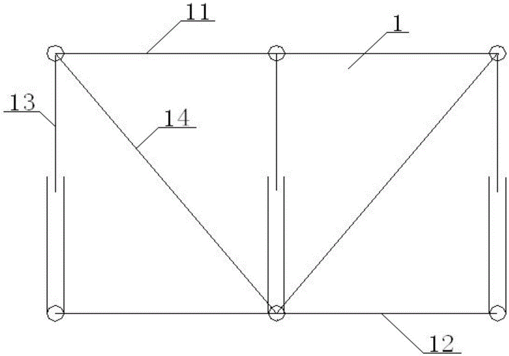
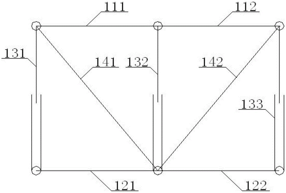
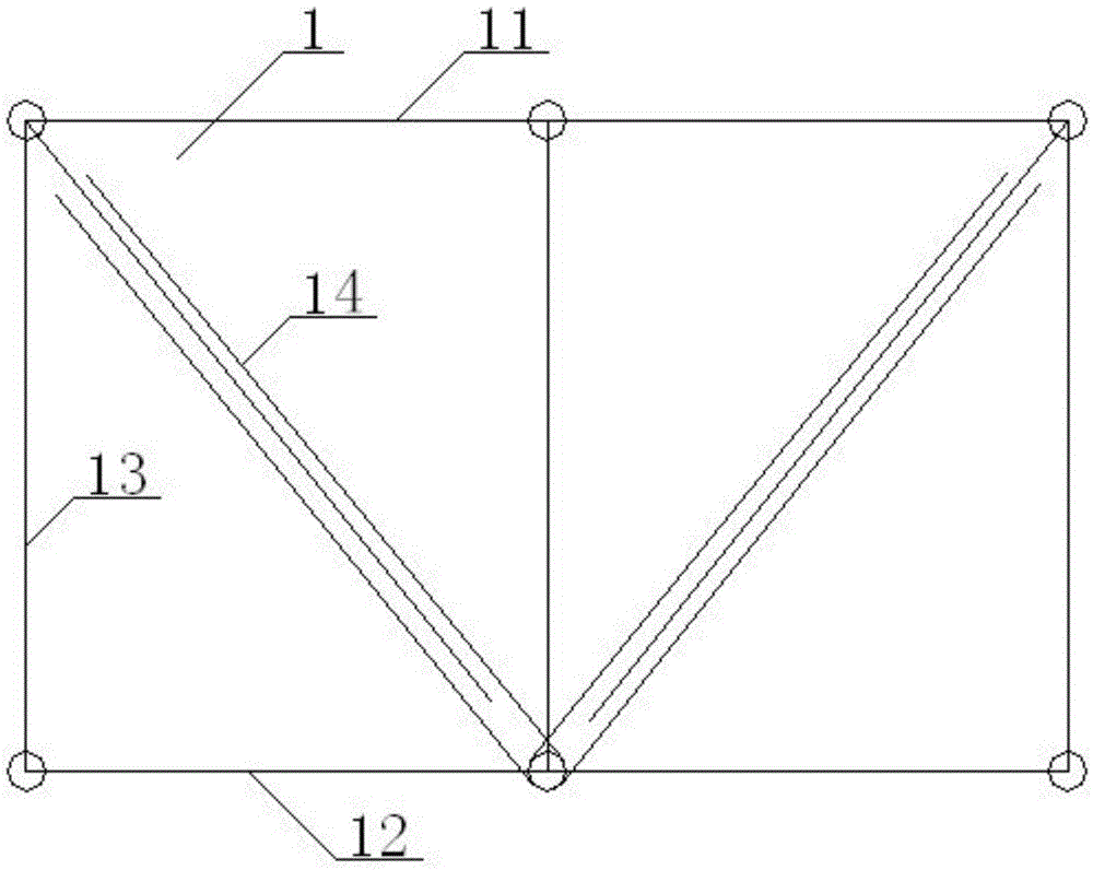
[0076] see Figure 1 to Figure 15 , a longitudinally foldable planar truss, the planar truss 1 includes an upper chord 11 and a lower chord 12 parallel to each other, and a vertical web 13 and a diagonal web 14 are connected between the upper chord 11 and the lower chord 12; The upper chord 11 includes a No. 1 upper chord 111 and a No. 2 upper chord 112. The right end of the No. 1 upper chord 111 is hinged with the left end of the No. 2 upper chord 112. The lower chord 12 includes a No. 1 lower chord 121 and a No. 2 lower chord. 122, the right end of the No. 1 lower chord 121 is hinged with the left end of the No. 2 lower chord 122; the vertical web 13 includes the No. 1 vertical web 131, the No. 2 vertical web 132, and the No. 3 vertical web 133, the upper end of the No. 1 vertical web 131 is hinged with the left end of the No. 1 upper chord 111, the lower end of the No. 1 vertical web 131 is hinged with the left end of the No. 1 lower chord 121, and the No. 2 vertical web T...
Embodiment 2
[0082] Basic content is the same as embodiment 1, the difference is:
[0083] see Figure 8 , the stretchable rod is a piston-type stretchable rod 2, and the piston-type stretchable rod 2 includes a connecting rod 21, an oil pipe 22, and an oil cylinder 23, and one end of the connecting rod 21 is provided with a transverse hole 25 at the end of the connecting rod. The other end of rod 21 is connected with piston 24, and piston 24 is arranged in the inside of oil cylinder 23, and the end portion of oil cylinder 23 is provided with cylinder bar end transverse hole 26, and the outside of oil cylinder 23 is provided with oil pipe 22 that is connected with oil cylinder 23, so The horizontal hole 25 at the rod end of the connecting rod and the horizontal hole 26 at the rod end of the oil cylinder are all matched with the pin 16 on the plane where the vertical plane truss 1 is located.
Embodiment 3
[0085] Basic content is the same as embodiment 1, the difference is:
[0086] see Figure 9 , the stretchable rod is a screw-type stretchable rod 3, the screw-type stretchable rod 3 includes a screw 31, a nut 32, a sleeve 33, and one end of the screw 31 is provided with a screw rod end transverse hole 35, and the outer side of the end is An electric wire 34 connected to the screw rod 31 is provided, the electric wire 34 is connected to the motor, the other end of the screw rod 31 is matched with the nut 32 arranged at one end of the casing 33, and the part where the screw rod 31 passes through the nut 32 is located inside the sleeve pipe 33, The other end of the casing 33 is provided with a casing rod end transverse hole 36, and the screw rod end transverse hole 35 and the casing rod end transverse hole 36 are all matched with the pin 16 on the plane where the vertical plane truss 1 is located.
PUM
 Abstract
Description
Claims
Application Information
 - R&D
- Intellectual Property
- Life Sciences
- Materials
- Tech Scout
- Unparalleled Data Quality
- Higher Quality Content
- 60% Fewer Hallucinations
Browse by: Latest US Patents, China's latest patents, Technical Efficacy Thesaurus, Application Domain, Technology Topic, Popular Technical Reports.
© 2025 PatSnap. All rights reserved.Legal|Privacy policy|Modern Slavery Act Transparency Statement|Sitemap|About US| Contact US: help@patsnap.com