A Ring Accelerated Loading Experimental System

An accelerated loading and experimental system technology, which is applied in the field of loop accelerated loading experimental systems, can solve problems such as low speed, high energy consumption, and actual inconsistency, and achieve the effects of increasing experimental speed, low energy consumption, and high reliability

Active Publication Date: 2018-01-05
SHANDONG JIAOTONG UNIV
View PDF8 Cites 1 Cited by
  • Summary
  • Abstract
  • Description
  • Claims
  • Application Information

AI Technical Summary

Problems solved by technology

It solves the problems of high energy consumption, low speed and inconsistency with reality

Method used


Image

  • A Ring Accelerated Loading Experimental System
  • A Ring Accelerated Loading Experimental System
  • A Ring Accelerated Loading Experimental System

Examples


Embodiment 1

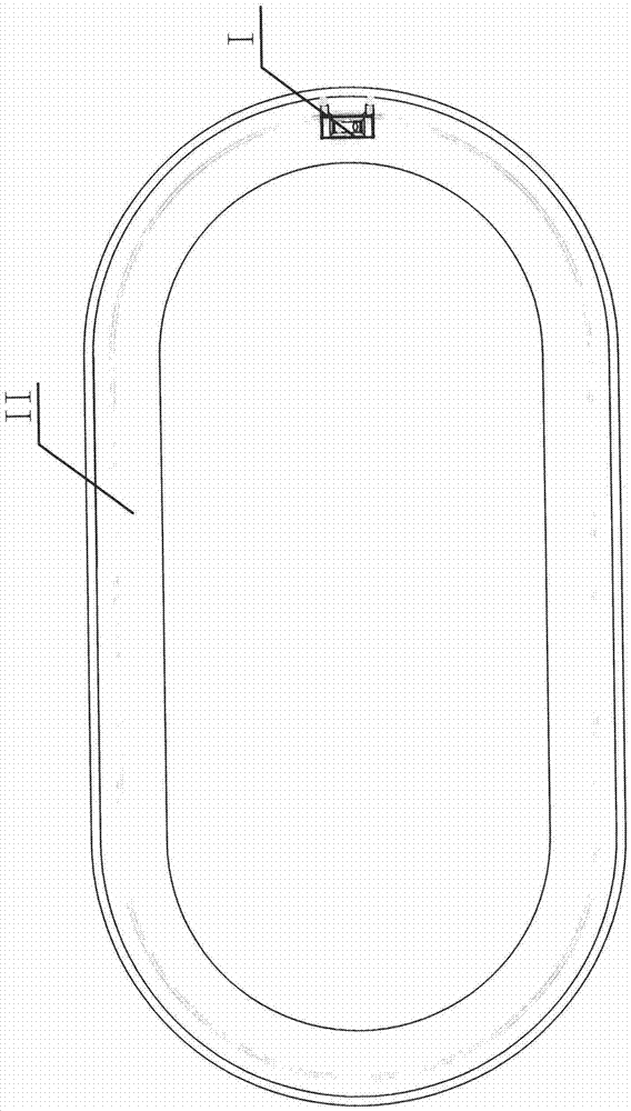
[0031] as attached figure 1 As shown, a loop accelerated loading test system of the present invention includes a loading car I and a ring test track II used with the loading car I.

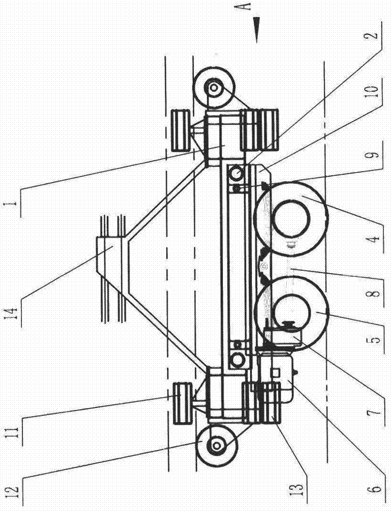
[0032] as attached Figure 2-4 As shown, the loading vehicle 1 includes an upper frame 1, a guide post 2, a guide sleeve 3, a driving wheel 4, a driven wheel 5, a motor 6, a reducer 7, a transmission shaft 8, a traverse screw 9, and a lower frame 10. Guide wheel 11, balance wheel 12, lateral support wheel 13, third rail receiver 14, the bottom of the upper frame 1 is horizontally provided with guide posts 2 and traversing screw 9 parallel to each other, and guide posts 2 are provided with There is a guide sleeve 3, the lower frame 10 is arranged on the guide sleeve 3, and the lower frame 10 is provided with a screw nut, a driving wheel 4 and a power mechanism connected with the driving wheel 4, the wheel shaft of the driving wheel 4 is connected to the guide Column 2 is parallel.

[0033] The t...

Embodiment 2

[0039] as attached figure 1 As shown, a loop accelerated loading test system of the present invention includes a loading car I and a ring test track II used with the loading car I.

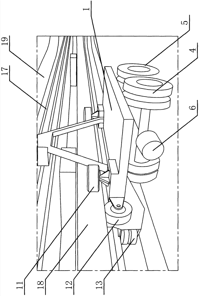
[0040] as attached Figure 5 As shown, the loading vehicle 1 includes an upper frame 1, a guide column 2, a guide sleeve 3, a driving wheel 4, a motor 6, a reducer 7, a transmission shaft 8, a traverse screw 9, a lower frame 10, and a guide wheel 11. The balance wheel 12, the lateral support wheel 13, the third rail receiver 14, the bottom of the upper frame 1 is horizontally provided with a guide post 2 and a traverse screw 9, and the guide post 2 is provided with a guide sleeve 3, get off The frame 10 is arranged on the guide sleeve 3 . The lower frame 10 is provided with a lead screw nut, a drive wheel 4, a motor 6, a speed reducer 7, and a transmission shaft 8, the motor 6 is connected with the transmission shaft 8 through the speed reducer 7, and the transmission shaft 8 is connected with t...


PUM


Abstract

The invention provides a loop accelerated loading testing system, which comprises a loading vehicle and an annular testing loop, wherein the loading vehicle comprises an upper vehicle frame, a lower vehicle frame, a guide column, a guide sleeve, a transverse movement lead screw, a driving wheel and a power mechanism; the guide column and the transverse movement lead screw which are parallel mutually are horizontally arranged at the bottom part of the upper vehicle frame; the guide sleeve is arranged on the guide column; the lower vehicle frame is arranged on the guide sleeve; a lead screw nut, the driving wheel and the power mechanism are arranged on the lower vehicle frame; the front end and the rear end of the upper vehicle frame are provided with the guide wheels, balancing wheels and side supporting wheels respectively; a third rail collector is also arranged on the upper vehicle frame; the annular testing loop comprises an annular vertical wall, crossbeams, a third rail and an annular guide rail; the inner side of the annular vertical wall is uniformly provided with a plurality of crossbeams; and the annular guide rail is arranged below the crossbeams. A driving and driven dual-wheel group rolling mode can be realized, which is consistent with the actual road rolling condition by a vehicle; by adopting the third rail mobile power supply mode, the testing speed and the testing effects are improved; and by adopting the scheme with the annular guide wheel and the guide wheels, the structure is simple, the reliability is high, and the power consumption is low.

Description

(1) Technical field [0001] The invention relates to an experimental device for accelerated loading of roads, in particular to an experimental system for accelerated loading of loops. (2) Background technology [0002] The loop acceleration loading test is a road acceleration loading test method. At present, the loop acceleration loading vehicle only has a single active wheel set to load, which is inconsistent with the actual rolling form of the vehicle on the road surface; the trolley line mobile power supply method is adopted, and the test speed is low. The effect is poor; in addition, the running guide structure of the loading vehicle is complicated, the reliability is low, and the energy consumption is large. (3) Contents of the invention [0003] The technical task of the present invention is to provide a loop accelerated loading experiment system aiming at the deficiencies of the prior art. It solves the problems of high energy consumption, low speed and inconsistenc...

Claims


Application Information

Patent Timeline
IPC IPC(8): G01M17/007
CPCG01M17/007
Inventor 冯晋祥国兴玉张鹏张吉卫贾倩管志光吴清珍王慧君韩鹰
Owner SHANDONG JIAOTONG UNIV
Why Eureka
Try Eureka