
Insulator zero value comprehensive test device

A testing device and insulator technology, which is applied in the direction of measuring device, testing dielectric strength, measuring electricity, etc., can solve the problems of large safety risks, high labor intensity of operators, and easy occurrence of missed testing, and achieves good data repeatability and improved Test efficiency and improve work efficiency

Inactive Publication Date: 2016-04-06
STATE GRID CORP OF CHINA +1
View PDF5 Cites 0 Cited by
  • Summary
  • Abstract
  • Description
  • Claims
  • Application Information

AI Technical Summary

Problems solved by technology

[0002] At present, the zero and low value test method of porcelain insulators on transmission lines is to use a pistol tester, which has the following problems: (1) The test results are displayed by dial pointers, and the numerical results are not accurate, and cannot accurately reflect the insulator resistance; (2) During the test, there is no prompt for the insulator whose insulation resistance meets the requirements. When the contact between the contact and the steel cap of the insulator is not in good contact and the test result is not obtained, the instrument also does not have any prompt, which is prone to missed testing; (3) The operator needs to hold the test by hand The instrument handle prevents the instrument from falling, and it is inconvenient to carry. It is necessary to pull the "trigger" with fingers during the test, and it is necessary to change the position on the insulator string during the test. However, the existing equipment is not conducive to testing while moving on the insulator string. Big safety risk, and for the insulator strings at different positions of far and near, high and low, the labor intensity of the operator is high, and the measurement is time-consuming and laborious

Method used


Image

  • Insulator zero value comprehensive test device
  • Insulator zero value comprehensive test device

Examples


Embodiment Construction

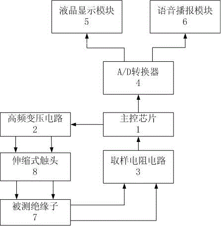
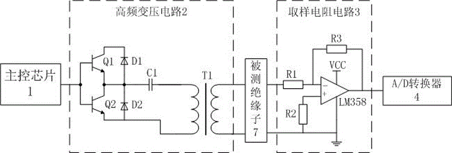
[0015] Attached below Figure 1~2 The present invention is further described.

[0016] refer to Figure 1~2 : The embodiment comprises an insulating shell, a main control chip 1 arranged in the insulating shell, a high frequency transformer circuit 2, a sampling resistance circuit 3, an A / D converter 4, a liquid crystal display module 5 and a voice broadcast module 6; the high voltage The output end of the frequency conversion circuit 2 is provided with telescopic contacts 8; At the input terminal of the tested insulator 7, the output terminal of the tested insulator 7 is connected to the input terminal of the sampling resistance circuit 3, and the output terminal of the sampling resistance circuit 3 is connected to the input terminal of the main control chip 1. The video and audio signal output terminal of the control chip 1 is connected to the liquid crystal display module 5 and the voice broadcast module 6 through the A / D converter 4; one side of the insulating shell is p...


PUM


Abstract

The invention discloses an insulator zero value comprehensive test device and belongs to the measuring instrument field. The insulator zero value comprehensive test device comprises an insulation casing, a main control chip arranged in the insulation casing, a high frequency transformation circuit, a sampling resistor circuit, an A / D converter, a liquid crystal display module and a voice broadcast module, wherein an output end of the high frequency transformation circuit is provided with a telescopic contact, a control signal output end of the main control chip is connected with the high frequency transformation circuit, the telescopic contact of the high frequency transformation circuit is connected with an input end of a detected insulator, an output end of the detected insulator is connected with an input end of the main control chip through the sampling resistor circuit, a video audio signal output end of the main control chip is connected with the liquid crystal display module and the voice broadcast module through the A / D converter, and the telescopic contact comprises a telescopic insulation rod and a conductive probe tip connected with an end portion of the telescopic insulation rod. The insulator zero value comprehensive test device is applicable to insulators with various disk diameters, is convenient to use and improves safety and work efficiency in the test process.

Description

technical field [0001] The invention belongs to the field of measuring instruments, in particular to an insulator zero-value comprehensive test device, which is suitable for insulators with various disc diameters. Background technique [0002] At present, the zero and low value test method of porcelain insulators on transmission lines is to use a pistol tester, which has the following problems: (1) The test results are displayed by dial pointers, and the numerical results are not accurate, and cannot accurately reflect the insulator resistance; (2) During the test, there is no prompt for the insulator whose insulation resistance meets the requirements. When the contact between the contact and the steel cap of the insulator is not in good contact and the test result is not obtained, the instrument also does not have any prompt, which is prone to missed testing; (3) The operator needs to hold the test by hand The instrument handle prevents the instrument from falling, and it i...

Claims


Application Information

Patent Timeline
Patent Type & Authority Applications(China)
IPC IPC(8): G01R31/12G01R27/08
CPCG01R31/1245G01R27/08
Inventor 冯红革刘增炜李立峰
Owner STATE GRID CORP OF CHINA
Learn More