Electric-field-sensed lightning rod capable of lifting automatically

An automatic lifting and lightning rod technology, applied in circuits, electrical components, corona discharge devices, etc., can solve the problems of laborious and laborious installation and removal of fixed lightning rods, damage to concealment effects, damage to landscape effects, etc., to achieve reliable and effective active protection. Thunder, does not expose the hidden body, does not affect the effect of the landscape

Inactive Publication Date: 2016-04-06
WUHAN HONGMEN ELECTRICAL TECH CO LTD
View PDF7 Cites 8 Cited by
  • Summary
  • Abstract
  • Description
  • Claims
  • Application Information

AI Technical Summary

Problems solved by technology

This kind of lightning rod (hereinafter referred to as "fixed lightning rod") has the following disadvantages in application: (1) It affects the landscape: in tourist attractions (such as ancient buildings, old trees, high-end places, etc.), the existence of fixed lightning rods is incompatible with the surrounding landscape, Destroying the landscape effect; (2) destroying the concealment effect: military facilities (such as temporary positions, weapon systems, etc.) need good concealment, and the existence of fixed lightning rods exposes military facilities; Temporary construction sites, mobile vehicles, offshore operating platforms, etc.) need to constantly change the operating location, and the installation and removal of fixed lightning rods are laborious and laborious
The Chinese patent with the notification number CN201478691U discloses a foldable field-varying discharge lightning rod. The height of the lightning rod can be adjusted to a certain extent, but the lifting of the lightning rod also requires manual judgment and manual operation.

Method used


Image

  • Electric-field-sensed lightning rod capable of lifting automatically
  • Electric-field-sensed lightning rod capable of lifting automatically

Examples


Embodiment Construction

[0027] The technical solutions of the present invention will be further described below in conjunction with the accompanying drawings.

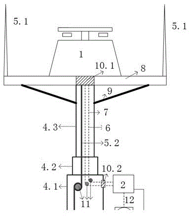
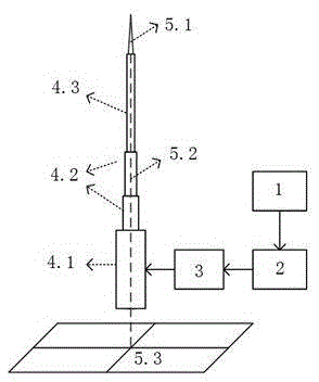
[0028] See figure 2 , In this embodiment, the electric field measuring instrument (1) adopts a ground electric field instrument, that is, a field mill. The lifting rod (4) adopts a pneumatic lifting rod, made of aluminum alloy, and is divided into 3 sections, each section is the base (4.1), the middle end telescopic rod (4.2) and the upper end telescopic rod (4.3), and the length of each section is 3 The connection between each section is sealed by a sealing ring, and the whole is equivalent to a multi-section cylinder. The drive unit (3) is an electric air pump, and its motor is connected to the mains through a relay to realize forward and reverse rotation of the motor. The electric field measuring instrument (1) and the electric control unit (2) are connected through the electric field signal line (7), the electric control unit (2) and t...


PUM


Abstract

The invention discloses an electric-field-sensed lightning rod capable of lifting automatically. The lightning rod comprises an electric field measuring instrument (1), an electric control unit (2), a driving unit (3), a lifting rod (4) and a lightning rod body (5), wherein the electric field measuring instrument (1), the electric control unit (2) and the driving unit (3) are connected in sequence; the lightning rod body (5) comprises a lightning arresting needle (5.1), a downlead wire (5.2) and a grounding apparatus (5.3); the downlead wire (5.2) is connected with the lightning arresting needle (5.1) and the grounding apparatus (5.3); and the lightning arresting needle (5.1) is positioned at the top end of the lifting rod (4). The lifting of the lightning rod is controlled by sensing whether thunder cloud exists or not so as to realize active lightning protection; when the lightning rod senses the existence of thunder cloud in the air, the lightning rod lifts up automatically for realizing lightning protection; and when the thunder cloud disappears, the lightning rod is atomically folded, so that the intelligent control of the lightning rod is realized.

Description

technical field [0001] The invention belongs to the technical field of lightning protection, and in particular relates to an electric field sensing automatic lifting lightning rod. Background technique [0002] Lightning rods are devices used to protect buildings and the like from lightning strikes. When a thunderstorm cloud occurs in the air, the lightning rod distorts the electric field on the ground, forms a local electric field concentration at the top of the lightning rod, guides the lightning to discharge to the lightning rod, and then introduces the lightning current into the earth through the down conductor and the grounding device, so that the protected object is not struck by lightning. . [0003] Once the traditional lightning rod is installed, its installation location and height are fixed. This kind of lightning rod (hereinafter referred to as "fixed lightning rod") has the following disadvantages in application: (1) Impact on the landscape: in tourist attract...

Claims


Application Information

Patent Timeline
Patent Type & Authority Applications(China)
IPC IPC(8): H01T19/04
CPCH01T19/04
Inventor 阮江军唐烈峥龚若涵
Owner WUHAN HONGMEN ELECTRICAL TECH CO LTD
Why Eureka
Try Eureka