Carrier aggregation device

A technology of carrier aggregation and clutter, which is applied to the separation device of the transmission path, digital transmission system, electrical components, etc., can solve the problem that 4 antennas are not feasible, and achieve the effect of reducing manufacturing cost and reducing interference

Active Publication Date: 2016-04-06
SANECHIPS TECH CO LTD
View PDF4 Cites 51 Cited by
  • Summary
  • Abstract
  • Description
  • Claims
  • Application Information

AI Technical Summary

Problems solved by technology

At present, the existing technologies of terminal carrier aggregation in the industry are generally a combination of low-band (LowBand) and high-band (HighBand), which can realize in-band continuous carrier aggregation (Intra-CA). Existing solutions are all based on a 4-antenna architecture, but for terminals, 4-antenna carrier aggregation is hardly achievable

Method used


Image

  • Carrier aggregation device
  • Carrier aggregation device
  • Carrier aggregation device

Examples


example 1

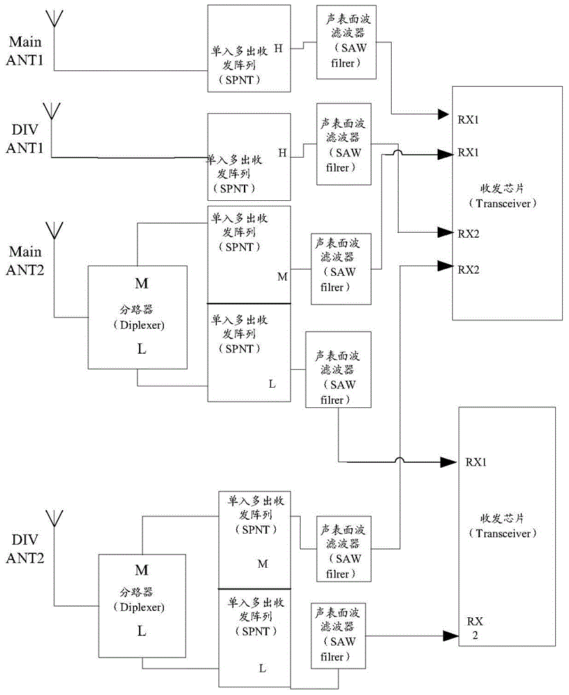
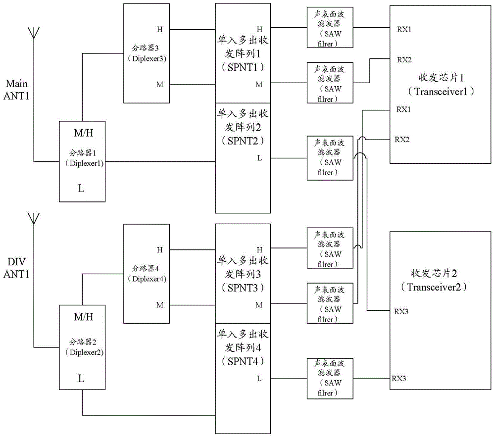
[0052] image 3 An exemplary structural diagram of a carrier aggregation device provided by an embodiment of the present invention, as shown in image 3 As shown, the signal enters the carrier aggregation device through the transceiver antennas (MainANT and DIVANT), and then enters the RF transceiver chip (Transceiver) through the RF front-end; the RF front-end includes: a power divider (Diplexer), an antenna switch, and a filter; exemplary, image 3 The pre-stage RF antenna switch in the middle adopts SPNT transceiver array, the filter adopts SAWfilter, MainANT and DIVANT respectively complete the main set and diversity reception of high frequency band (HBand), middle frequency band (MBand) and low frequency band (LBand); image 3 As shown, after the signal enters from MainANT, it is decomposed into one low-frequency signal and one medium-frequency and high-frequency mixed signal through Diplexer1. The low-frequency signal is directly connected to the low-frequency signal rec...

example 2

[0056] Figure 4 Another exemplary structural diagram of a carrier aggregation device provided by an embodiment of the present invention, Figure 4 exist image 3 On the basis of , Diplexer3 and Diplexer4 are replaced by LNA1 and LNA2, and the rest of the devices are changed. Therefore, the same devices use the same reference signs;

[0057] The signal enters the carrier aggregation device through the transceiver antenna (MainANT and DIVANT), and then enters the RF transceiver chip (Transceiver) through the RF front-end; the RF front-end includes: power splitter (Diplexer), antenna switch and filter; Figure 4 As shown, after the signal enters from MainANT, it is decomposed into one low-frequency signal and one medium-frequency and high-frequency mixed signal through Diplexer1. The low-frequency signal is directly connected to the low-frequency signal receiving end (L terminal) of SPNT2; It is decomposed into one high-frequency signal and one low-frequency signal, and then c...


PUM


Abstract

The invention discloses a carrier aggregation device, which comprises a first transmitting and receiving antenna, a second transmitting and receiving antenna, a first radio frequency front end, a second radio frequency front end and a radio frequency transmitting and receiving chip, wherein signals received by the first transmitting and receiving antenna are divided into a way of high-frequency signals, a way of intermediate-frequency signals and a way of low-frequency signals through the first radio frequency front end, and the three ways of signals enter the radio frequency transmitting and receiving chip respectively; and signals received by the second transmitting and receiving antenna are divided into a way of high-frequency signals, a way of intermediate-frequency signals and a way of low-frequency signals through the second radio frequency front end, and the three ways of signals enter the radio frequency transmitting and receiving chip respectively.

Description

technical field [0001] The present invention relates to the technical field of multi-mode mobile communication, and in particular to a carrier aggregation device. Background technique [0002] With the advent of 4G communication technology, in order to support higher rates, 3GPP proposed LTE Advance (LTE-A), which can support more bandwidth combinations to achieve resource integration and increase data service rates, especially in limited frequency band resources. In some cases, carrier aggregation can significantly improve the data rate. At present, the existing technologies for terminal carrier aggregation in the industry are generally a combination of low-band (LowBand) and high-band (HighBand), which can realize in-band continuous carrier aggregation (Intra-CA). Existing solutions are all based on a 4-antenna architecture, but for a terminal, carrier aggregation with 4 antennas is hardly achievable. Contents of the invention [0003] In order to solve existing techni...

Claims


Application Information

Patent Timeline
Patent Type & Authority Applications(China)
IPC IPC(8): H04L5/00
CPCH04B1/0057H04L5/001H04L5/00H04B1/005H04L5/14
Inventor 刘海广
Owner SANECHIPS TECH CO LTD
Why Eureka
Try Eureka