LED light supplement control circuit used for roller-shutter-type shutter exposure camera

A technology of rolling shutter and control circuit, which is applied in the direction of TV, electrical components, color TV, etc. It can solve problems such as difficult to obtain pictures and adjust the brightness of fill light, so as to improve the response speed, enhance the brightness, and solve the problem of overcurrent The effect of rushing phenomenon

Active Publication Date: 2016-04-06
HANGZHOU EBOYLAMP ELECTRONICS CO LTD
View PDF8 Cites 3 Cited by
  • Summary
  • Abstract
  • Description
  • Claims
  • Application Information

AI Technical Summary

Problems solved by technology

[0003] In the prior art, the supplementary light of the rolling shutter exposure camera is mainly the LED constant light. When the camera sends

Method used


Image

  • LED light supplement control circuit used for roller-shutter-type shutter exposure camera
  • LED light supplement control circuit used for roller-shutter-type shutter exposure camera
  • LED light supplement control circuit used for roller-shutter-type shutter exposure camera

Examples


Embodiment Construction

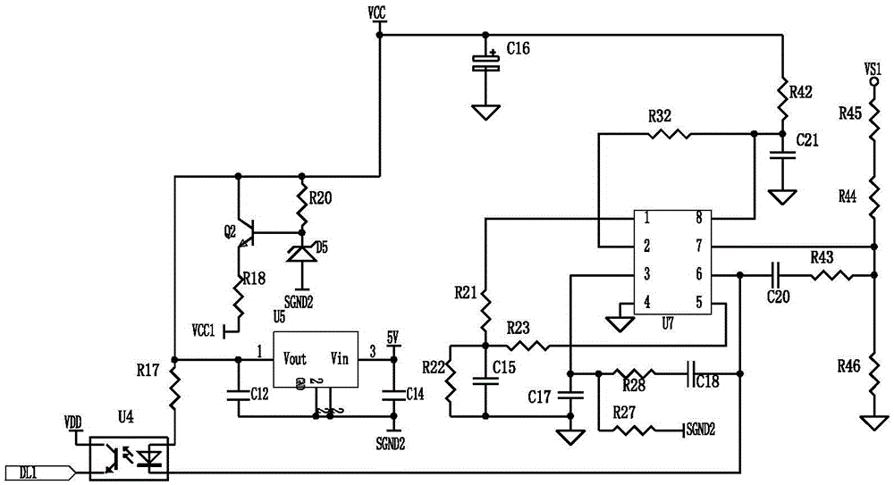
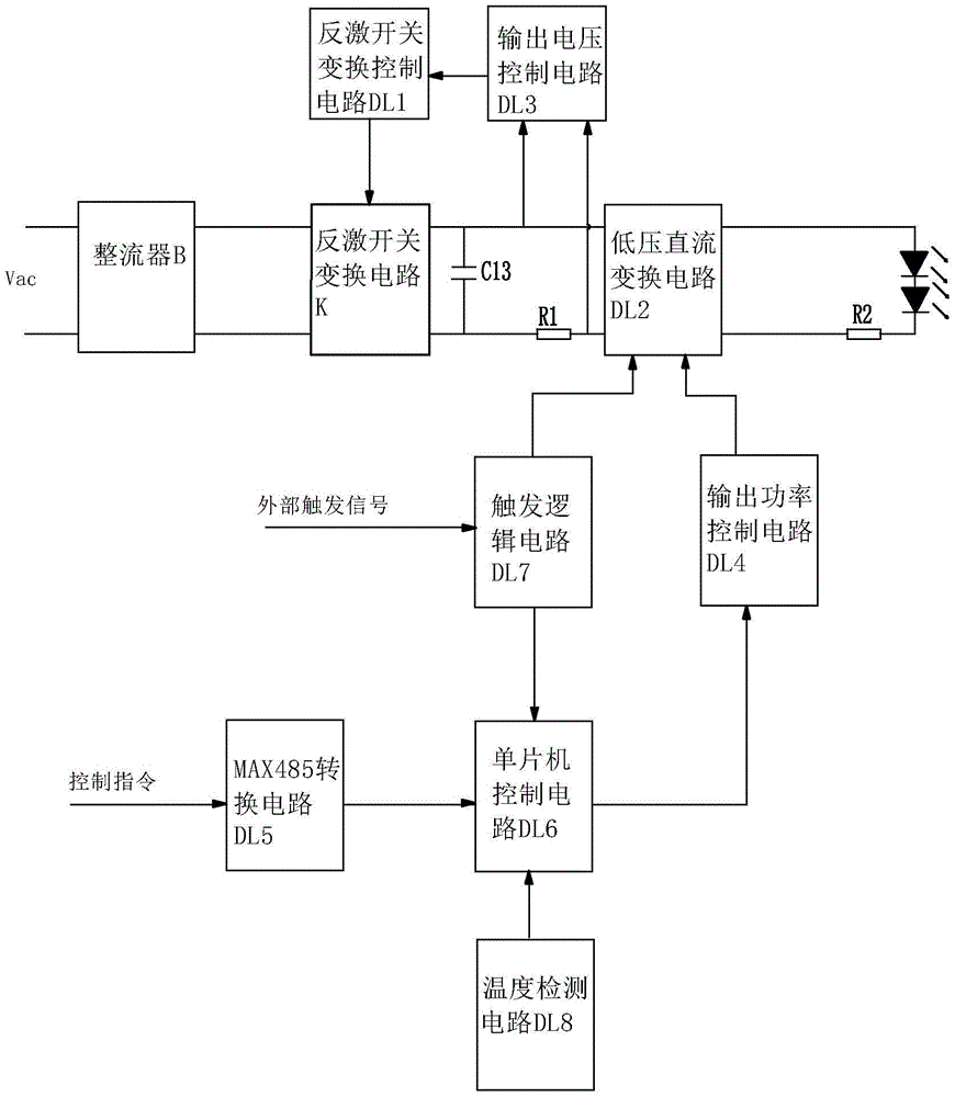
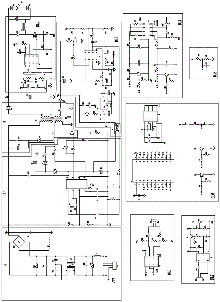
[0034] In this patent, the signal output terminal of the bright power control part in the output power control circuit DL4 circuit is connected to the high brightness power signal input terminal in the low-voltage DC conversion circuit DL2, so the signal output terminal of the above bright power control part and the high brightness power The signal input terminal actually refers to the same connection terminal, which is represented by Vf1; the signal output terminal of the low-power control part in the output power control circuit DL4 circuit is connected to the low-brightness power signal input terminal in the low-voltage DC conversion circuit DL2, so the above-mentioned low-power control Part of the signal output terminal and the low-brightness power signal input terminal actually refer to the same connection terminal, which are both represented by Vf2.

[0035] Below in conjunction with accompanying drawing this patent is described further.

[0036] like figure 1 and fig...


PUM


Abstract

The invention discloses an LED light supplement control circuit used for a roller-shutter-type shutter exposure camera. The circuit comprises a light supplement lamp source, a power supply circuit portion and a control circuit portion. The power supply circuit portion comprises a rectifier B, a flyback switch conversion circuit K and an output filtering energy storage capacitor C13 which are successively connected. The control circuit portion comprises a flyback switch conversion control circuit DL1, a low voltage conversion direct current circuit DL2, an output voltage control circuit DL3, a power control circuit DL4, a MAX485 conversion circuit DL5, a single chip microcomputer control circuit DL6 and a trigger logic circuit DL7. The circuit has advantages that a trigger response speed is rapid; a constant current effect of a LED light source is good; and constant bright power of an LED light supplement lamp source and high light power during a light supplement process can be set.

Description

technical field [0001] The invention relates to a monitoring camera circuit, in particular to an LED supplementary light control circuit for a rolling shutter exposure camera. Background technique [0002] The rolling shutter exposure camera has become an important camera equipment in the monitoring system and plays an increasingly important role because it can clearly capture the scene under low illumination conditions. In the process of taking pictures, strong light is needed to capture the scene clearly. Since the rolling shutter exposure camera adopts progressive exposure, the fill light needs to work in a constant current state, and the trigger response time of the fill light is very important. Yes, it needs to be turned on and off quickly when the camera is triggered. [0003] In the prior art, the supplementary light of a rolling shutter exposure camera is mainly an LED constant light. When the camera sends a trigger command, the LED constant light cannot adjust the ...

Claims


Application Information

Patent Timeline
IPC IPC(8): H04N5/235
Inventor 徐根达赵合昌徐辉高涛涛
Owner HANGZHOU EBOYLAMP ELECTRONICS CO LTD
Why Eureka
Try Eureka