
Simple Measuring Device for Clamping Force at Different Opening Degrees of Vascular Clips

A measuring device and a technique for vascular clips, applied in the field of medical devices, can solve the problems of inability to characterize, limit wide application, and poor availability of clips, and achieve the effects of preventing deformation under force, good measurement accuracy, and reducing experimental costs.

Inactive Publication Date: 2018-03-27
THE AFFILIATED DRUM TOWER HOSPITAL MEDICAL SCHOOL OF NANJING UNIV
View PDF5 Cites 0 Cited by
  • Summary
  • Abstract
  • Description
  • Claims
  • Application Information

AI Technical Summary

Problems solved by technology

But its disadvantages are as follows: 1. The availability of clips is poor: because the clamping force of ordinary vascular clips is unknown and not comparable, cerebral aneurysm clips with known calibration force are often used in this research, but their cost is high, which limits its wide application
2. It is impossible to measure the dynamic clamping force: because the clamping force of existing vascular clamps changes dynamically with the clamping depth and mouth opening, simply knowing the clamping force cannot meet the experimental needs; 3. Causes a certain amount of medical resources Waste: In theory, ordinary vascular clips can meet the experimental needs, but the use of high-cost and special-material cerebral aneurysm clips will cause a certain waste of rare medical resources
4. Unable to conduct factorial retrospective research: When analyzing the source of differences in models, it is impossible to qualitatively and quantitatively compare the sources of differences in injury intensity

Method used


Image

  • Simple Measuring Device for Clamping Force at Different Opening Degrees of Vascular Clips
  • Simple Measuring Device for Clamping Force at Different Opening Degrees of Vascular Clips
  • Simple Measuring Device for Clamping Force at Different Opening Degrees of Vascular Clips

Examples


Embodiment 1

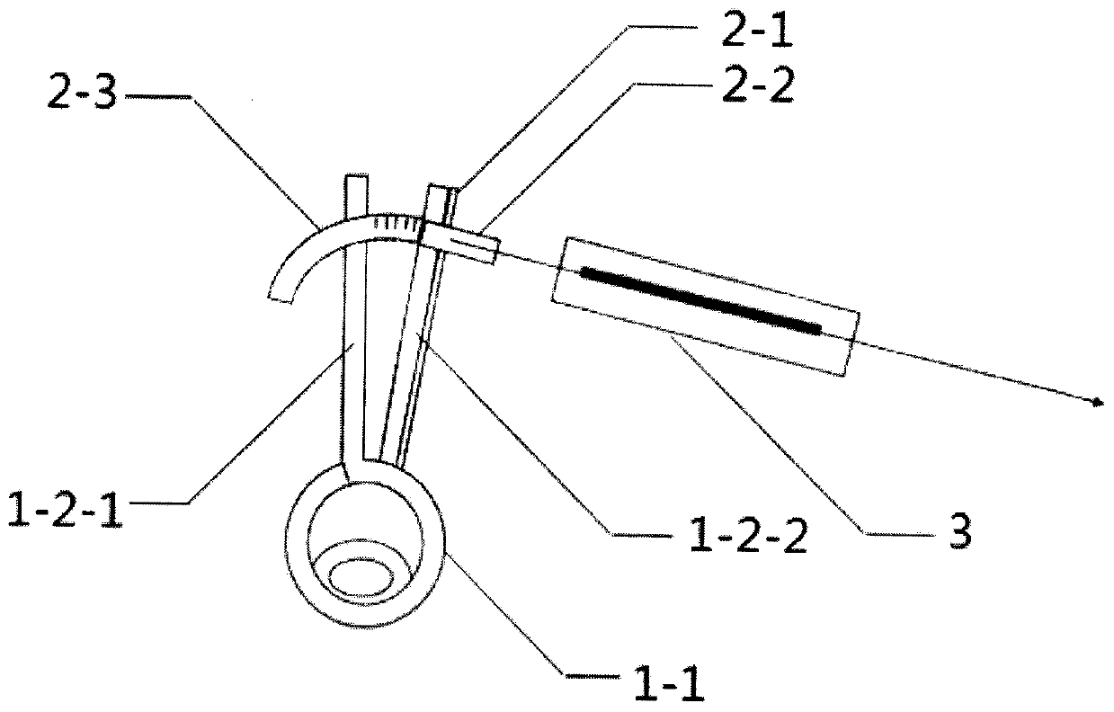
[0034] Measurement of clamping force with large mouth opening (take 4mm as an example)

[0035] (1) Ordinary vascular clamp 1 is placed flat on the table, with the left clamp arm 1-2-1 and the right clamp arm 1-2-2 facing straight ahead;

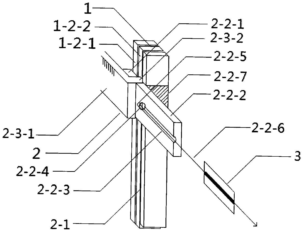
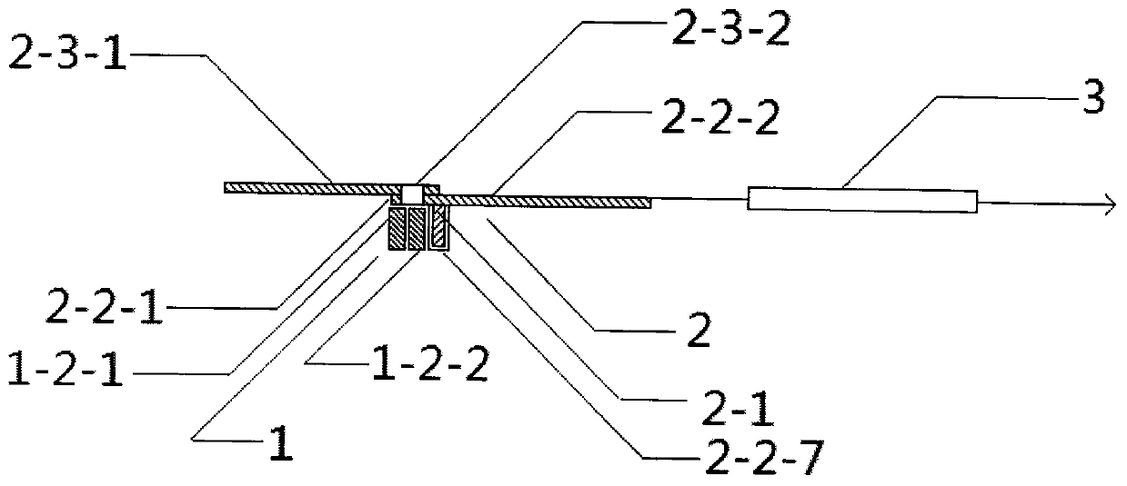
[0036] (2) The left and right surgical sutures are recorded as two sections A and B. A is used to fix the left clamp arm 1-2-1 on a nail, and B is divided into three sections for evenly binding the fixing piece 2- 1 On the right clamp arm 1-2-2, mark the point to be measured on the fixed piece 2-1;

[0037] In the step (2), the binding and fixing should be fastened firmly so as not to slip, and the number of turns of silk thread winding should be limited to 1 turn as much as possible when measuring the closing clamp force, so as to avoid affecting the initial opening degree of the vascular clamp 1 .

[0038] (3) Slide the ordinary scale 2-2 along the long axis direction of the fixed piece 2-1, so that the round hole 2-2-4 is aligned with th...

Embodiment 2

[0042] Determination of clamping force with small mouth opening (take 1mm as an example)

[0043] If the mouth opening is very small, the ordinary scale 2-2 can meet the measurement needs. This method can be used. The installation process is the same as above except that the arc scale 2-3 is not required. The specific operation process is as follows:

[0044] (1) Ordinary vascular clamp 1 is placed flat on the table, with the clamp arm facing straight ahead;

[0045] (2) The left and right surgical sutures are recorded as two sections A and B. A is used to fix the left clamp arm on a nail, and B is divided into three sections for evenly binding the fixing piece 2-1 on the right clamp arm. , mark the points to be measured on the fixed piece 2-1;

[0046] In the step (2), the binding and fixing should be fastened firmly so as not to slip, and the number of turns of silk thread winding should be limited to 1 turn as much as possible when measuring the closing clamp force, so as ...


PUM


Abstract

The invention relates to a simple measuring device for clamp force at different opening degrees of blood vessel clamps. The structure of the present invention is that the spring balance is connected to the core components, and the core components are connected to the blood vessel clamp; the blood vessel clamp includes a clip application site, a left clamp arm, and a right clamp arm, and the core component includes a fixed piece, a common scale, and an arc scale; The common scale includes a left part, a right part, a groove, a circular hole, a ring, a thread, and a slot; the arc-shaped scale includes a body and a head. The invention overcomes the defects of the cerebral aneurysm clip that the dynamic clipping force cannot be measured, the experimental requirements cannot be met, and the factorial retrospective research cannot be carried out. The invention has the advantages of measuring the clamping force of different opening degrees, reducing the cost of the experiment, good measuring accuracy, simple operation and the like.

Description

technical field [0001] The invention relates to the field of medical instruments, in particular to a simple measuring device for clamping force at different opening degrees of blood vessel clamps. Background technique [0002] Clamp spinal cord injury animal model is a more and more widely used model, which simulates the continuous compression of the local spinal cord after mechanical spinal cord injury in clinical practice, and is of great significance for studying the complex pathophysiological mechanism of spinal cord injury. [0003] Before the present invention was made, most of the cerebral aneurysm clips with ex-factory calibration force were used, and it was generally believed that the calibration force of the blood vessel clip was positively correlated with the degree of spinal cord injury. But its disadvantages are as follows: 1. The availability of clips is poor: because the clamping force of ordinary vascular clips is unknown and not comparable, cerebral aneurysm...

Claims


Application Information

Patent Timeline
Patent Type & Authority Patents(China)
IPC IPC(8): A61B17/122G01L1/04
CPCA01K2267/03A61B17/122G01L1/04
Inventor 荣辉马正良顾小萍张佐霞
Owner THE AFFILIATED DRUM TOWER HOSPITAL MEDICAL SCHOOL OF NANJING UNIV
Learn More