

Casting cleaning unit and method
A casting cleaning and casting technology, applied in the field of casting, can solve the problems of low worker quota, strong labor, low work efficiency, etc., and achieve the effects of simple mechanism structure, reliable and stable positioning, and low cost.
- Summary
- Abstract
- Description
- Claims
- Application Information
AI Technical Summary
Problems solved by technology
Method used
Image

Examples
Embodiment 1
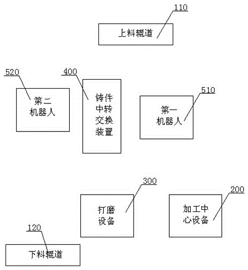
[0045] Embodiment one: see Figure 1-Figure 4 , as shown in the legend therein, a casting cleaning unit,
[0046] Including the first conveying roller table 110, the second conveying roller table 120, the machining center equipment 200, the grinding equipment 300, the casting transfer exchange mechanism 400, the first robot 510 and the second robot 520, the machining center equipment 200 is set on the first conveying roller One side of the road 110, and the grinding device 300 is arranged on one side of the second conveying roller table 120.
[0047] The machining center equipment 200 is a vertical machining center equipment, which is mainly used for casting pre-processing and large flash removal.
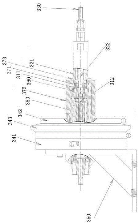
[0048] The grinding equipment 300 includes a processing device and a fixture. The above-mentioned processing device includes an air motor, a handle assembly, and a tool that are sequentially connected along the power output direction. The above-mentioned air motor includes a motor...
Embodiment 2
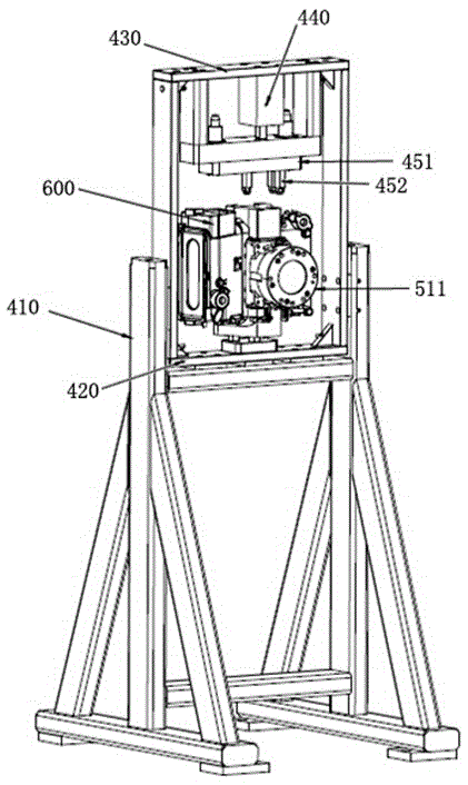
[0071] see Figure 5 , as shown in the legend therein, the rest are the same as in Embodiment 1, the difference is that the above-mentioned casting cleaning unit also includes a robot gripper automatic exchange mechanism, and the robot gripper automatic exchange mechanism includes a frame 710 and is installed on the frame The above-mentioned exchange station includes a positioning plate 721, and a card slot 722 is arranged on the positioning plate 721. The horizontal section of the card slot 722 is U-shaped, and the width dimension of the card slot 722 along the horizontal direction and along the horizontal direction The depth dimension of the direction matches the diameter of the connecting disc of the robot gripper.
PUM
 Abstract
Description
Claims
Application Information