Planar redundant robot

A technology of redundancy and robotics, applied in the field of robotics, can solve the problems of low positioning accuracy of planar robots, unreasonable layout of drive units, and large robot inertia, etc., to achieve increased rigidity, good stability and accuracy, and reduced moment of inertia Effect

Active Publication Date: 2016-04-13
HARBIN INST OF TECH
View PDF9 Cites 6 Cited by
  • Summary
  • Abstract
  • Description
  • Claims
  • Application Information

AI Technical Summary

Problems solved by technology

[0005] In order to solve the problem of low positioning accuracy of existing planar robots, the present invention further proposes a planar redundant robot
[0007] The beneficial effects of the present invention are: 1. The present invention realizes the structural innovation of the planar redundant robot, and solves the common problems in the prior art such as complex structure, large volume, unreasonable drive unit layout, large robot inertia, etc.

Method used


Image

  • Planar redundant robot
  • Planar redundant robot
  • Planar redundant robot

Examples


specific Embodiment approach 1

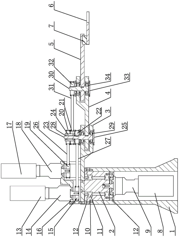
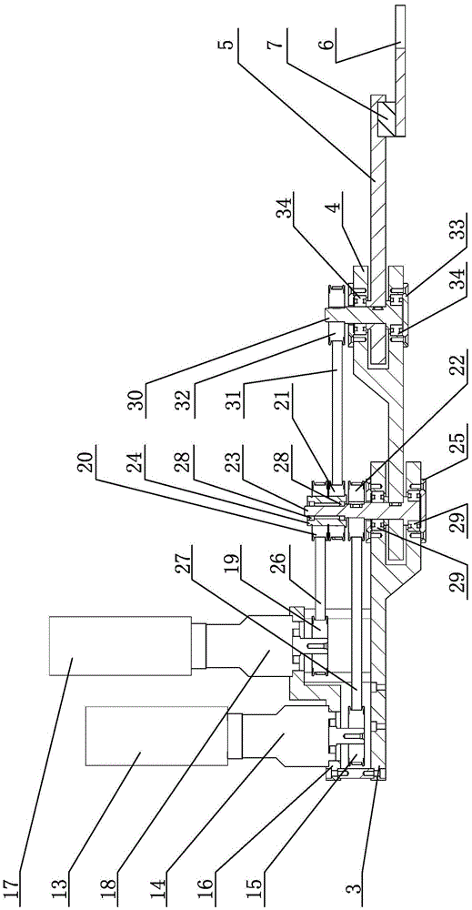
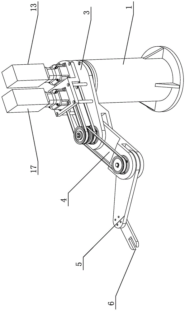
[0013] Specific implementation mode one: combine Figure 1 to Figure 3 Describe this embodiment, a planar redundant robot described in this embodiment includes a base 1, a first drive unit, a joint shaft 2, a support mechanism, a first link 3, a second link 4, and a third link 5. The operator 6, the second drive unit, the third drive unit, the first relay mechanism, the second relay mechanism, the sensor 7 and the drive unit bracket 16, the first drive unit is installed in the base 1, and the joint shaft 2 The support mechanism is installed in the base 1, the first drive unit is connected to the lower end of the joint shaft 2, the upper end of the joint shaft 2 is connected to one end of the first connecting rod 3, and the other end of the first connecting rod 3 passes through The first transfer mechanism is connected with one end of the second connecting rod 4, the other end of the second connecting rod 4 is connected with one end of the third connecting rod 5 through the sec...

specific Embodiment approach 2

[0015] Specific implementation mode two: combination Figure 1 to Figure 3 Describe this embodiment, the first drive unit of a kind of planar redundancy robot described in this embodiment includes a first drive motor 8 and a first reducer 9, the rotation shaft of the first drive motor 8 passes through the first reducer 9 and The lower end of joint axis 2 is connected. Other components and connections are the same as those in the first embodiment.

specific Embodiment approach 3

[0016] Specific implementation mode three: combination Figure 1 to Figure 3 Describe this embodiment, the support mechanism of a planar redundant robot described in this embodiment includes a sleeve 10, two first deep groove ball bearings 11 and two cover plates 12, the sleeve 10 is set on the joint shaft 2 , the upper end of the sleeve 10 is fixedly connected with the upper end of the base 1 through a cover plate 12, the lower end of the sleeve 10 is connected with the first reducer 9 through a cover plate 12, and the upper end and the lower end of the sleeve 10 are respectively provided with a The first deep groove ball bearing 11 and the two first deep groove ball bearings 11 are both sleeved on the joint shaft 2 . Other compositions and connections are the same as those in Embodiment 1 or 2.


PUM


Abstract

The invention discloses a planar redundant robot, relates to a robot, and specifically relates to a planar redundant robot. The invention aims at solving the problem of low location accuracy of the existing planar robot. The planar redundant robot disclosed by the invention comprises a base, a first drive unit, a joint shaft, a support mechanism, a first connection rod, a second connection rod, a third connection rod, a manipulator, a second drive unit, a third drive unit, a first transit mechanism, a second transit mechanism, a sensor and a drive unit support, wherein the first drive unit is installed in the base; the joint shaft is installed in the base through the support mechanism; the first drive unit is connected with the lower end of the joint shaft; the upper end of the joint shaft is connected with one end of the first connection rod; the other end of the first connection rod is connected with one end of the second connection rod through the first transit mechanism; and the other end of the second connection rod is connected with one end of the third connection rod through the second transit mechanism. The invention belongs to the field of robots.

Description

technical field [0001] The invention relates to a robot, in particular to a plane redundancy robot, which belongs to the field of robots. Background technique [0002] With the continuous development and progress of robot technology, monotonous and repetitive work should be done by robots. Especially in the labor-intensive assembly process of 3C products such as mobile phones, tablet computers, and PC peripherals. With the miniaturization of 3C products, the assembly operations are becoming more and more complicated. Traditional types of robots cannot complete such tasks well. Product assembly tasks, and complete such complex assembly tasks manually will lead to a significant increase in the work intensity of workers, and also affect the assembly quality of 3C products to a certain extent. In order to better cooperate with workers to complete assembly tasks and improve the quality of assembly, many foundries have begun to use planar robots as auxiliary equipment for manual ...

Claims


Application Information

Patent Timeline
Patent Type & Authority Applications(China)
IPC IPC(8): B25J9/10B25J9/04
CPCB25J9/042B25J9/104B25J9/109
Inventor 刘玉斌戴骞李长乐赵杰高永生
Owner HARBIN INST OF TECH
Why Eureka
Try Eureka