Serial flexible driving joint having steel wire transmission function

A joint and flexible technology, which is applied in the field of steel wire transmission series flexible drive joints, can solve the problems of series flexible drive joint structure redundancy, poor space adaptability, poor motion stability, etc. The effect of small loads

Active Publication Date: 2016-04-13
HARBIN INST OF TECH
View PDF6 Cites 11 Cited by
  • Summary
  • Abstract
  • Description
  • Claims
  • Application Information

AI Technical Summary

Problems solved by technology

[0003] In order to solve the problems of redundant structure, large mass, poor space adaptability and poor motion stability of the existing series flexible drive joints, the present invention provides a steel wire transmission series flexible drive joint

Method used


Image

  • Serial flexible driving joint having steel wire transmission function
  • Serial flexible driving joint having steel wire transmission function
  • Serial flexible driving joint having steel wire transmission function

Examples


specific Embodiment approach 1

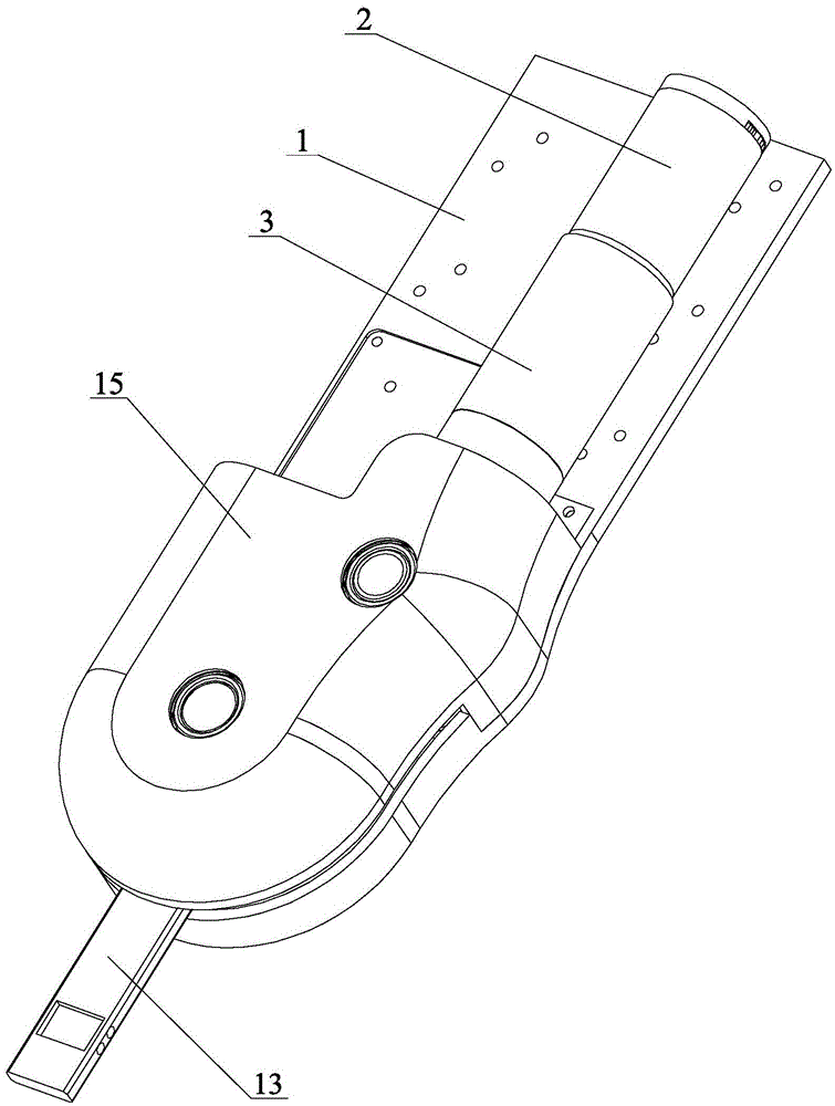
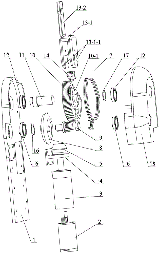
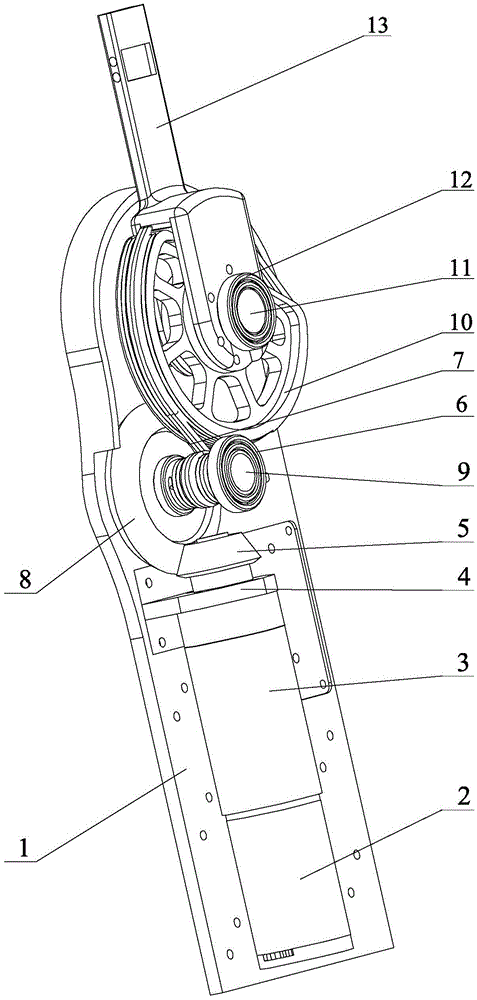
[0015] Specific implementation mode one: combine Figure 1 to Figure 5 Describe this embodiment. This embodiment includes a support base plate 1, a joint drive assembly and an external support housing 15. The joint drive assembly includes a drive motor 2, a planetary reducer 3, a support flange 4, a reversing pinion bevel gear 5, and a transmission wire rope 7. Reversing large bevel gear 8, small sheave 9, large sheave 10, large sheave shaft 11, output piece 13, rope pretensioning device 14, two small sheave support bearings 6 and two large sheave shaft support bearings 12. The output part 13 is composed of an inverted U-shaped shift fork 13-1 and an output rod 13-2. The lower end of the inverted U-shaped wall of the inverted U-shaped shift fork 13-1 is provided with a mounting groove 13-1-1, and the output rod 13-1 2. Set on the inverted U-shaped shift fork 13-1, the output rod 13-2 is opposite to the inverted U-shaped wall on one side of the inverted U-shaped shift fork 13-1...

specific Embodiment approach 2

[0021] Specific implementation mode two: combination Figure 4 To illustrate this embodiment, the small sheave 9 of this embodiment is provided with a small sheave spiral groove 9-1, and the initial position and the end position of the small sheave spiral groove 9-1 are respectively provided with a transmission rope fixing hole 9-2 . Other components and connections are the same as those in the first embodiment.

specific Embodiment approach 3

[0022] Specific implementation mode three: combination Figure 5 The present embodiment is described. The large sheave 10 of the present embodiment is provided with a large sheave helical groove 10-2. Other components and connections are the same as those in the second embodiment.


PUM


Abstract

The invention relates to a robot driving joint, in particular to a serial flexible driving joint having a steel wire transmission function. A reversing bevel pinion is in key connection with an output shaft of a planetary reducer, a reversing big bevel gear is meshed with the reversing bevel pinion and is in key connection with a small rope wheel, one end of a transmission steel wire rope winds around the small rope wheel, the other end of the transmission steel wire rope winds around a big rope wheel, then winds around the small rope wheel and is fixed on the small rope wheel, the big rope wheel is in key connection with a big rope wheel shaft, a rope pre-tightening device is located above a plane, the rope pre-tightening device and one end of a plane of the big rope wheel are arranged in an inverted U-shaped groove of an inverted U-shaped shifting fork, a joint driving assembly is arranged on one end surface of one side of a supporting bottom plate, an external supporting casing is buckled on the supporting bottom plate, an output rod is exposed out of the supporting bottom plate and the external supporting casing, two small rope wheel supporting bearings and two big rope wheel shaft supporting bearings are supported on the corresponding supporting bottom plate and the corresponding external supporting casing respectively. The flexible driving joint is applied to a joint part of a robot.

Description

technical field [0001] The invention relates to a robot drive joint, in particular to a steel wire transmission series flexible drive joint. Background technique [0002] The robot-driven joint is a crucial component of the overall system of the robot, and the flexible-driven joint can effectively reduce the impact, improve the service life of the robot, and has good human-computer interaction, so the joint design based on the flexible drive is gradually emerging. The serial flexible driving method has the advantages of natural compliance, biomechanical similar characteristics and good buffer function, so it has been widely used in bionic robots, rehabilitation robots, exoskeleton machines and fields with strong human-computer interaction. Traditional serial flexible drive joints require a dedicated flexible component in series, the overall structure is redundant, the weight of the joint is large, and the structural adaptability is poor. At the same time, it is difficult to ...

Claims


Application Information

Patent Timeline
Patent Type & Authority Applications(China)
IPC IPC(8): B25J17/02
CPCB25J17/0208B25J17/025
Inventor 朱延河郑天骄赵杰
Owner HARBIN INST OF TECH
Why Eureka
Try Eureka