A solar wing layout structure of a high-precision spacecraft

A layout structure and spacecraft technology, applied in the field of spacecraft, can solve problems such as reducing the attitude stability of the spacecraft platform, reducing the attitude stability of the platform, and thermal flutter of the solar wing, so as to achieve simple configuration, improve attitude stability, Reduce the effect of micro-vibration

Active Publication Date: 2017-12-29
SHANGHAI SATELLITE ENG INST
View PDF5 Cites 0 Cited by
  • Summary
  • Abstract
  • Description
  • Claims
  • Application Information

AI Technical Summary

Problems solved by technology

The current spacecraft platform basically uses movable solar wings, and the connection stiffness with the platform is low. When the spacecraft performs orbit transfer or attitude adjustment, it will produce micro-vibration, thereby reducing the attitude stability of the platform.
In addition, in order to minimize the weight of the spacecraft, the solar wing basically uses lightweight materials such as honeycomb sandwich panels, which further aggravates the micro-vibration
Seriously, when the solar wing enters and exits the shadow of the sun, due to the drastic change of the external heat flow, it may cause thermal flutter of the solar wing, which seriously reduces the attitude stability of the spacecraft platform

Method used


Image

  • A solar wing layout structure of a high-precision spacecraft
  • A solar wing layout structure of a high-precision spacecraft
  • A solar wing layout structure of a high-precision spacecraft

Examples


Embodiment Construction

[0014] The present invention will be described in detail below in conjunction with specific embodiments. The following examples will help those skilled in the art to further understand the present invention, but do not limit the present invention in any form. It should be noted that those skilled in the art can make several modifications and improvements without departing from the concept of the present invention. These all belong to the protection scope of the present invention.

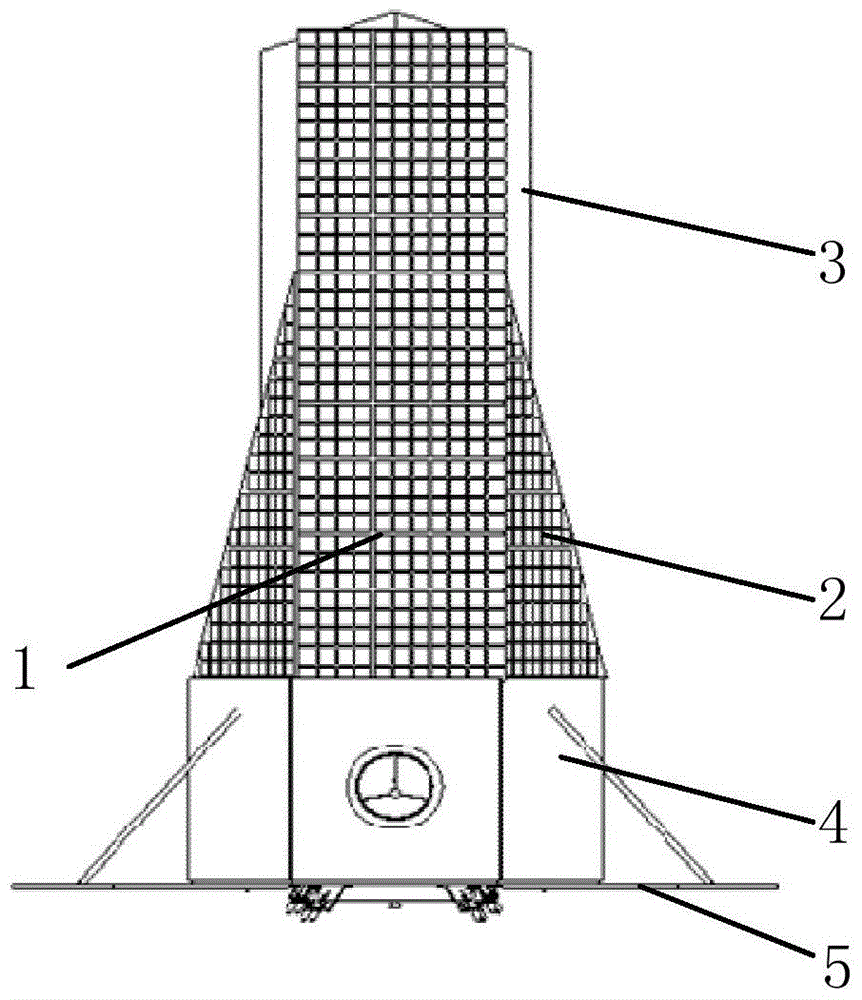
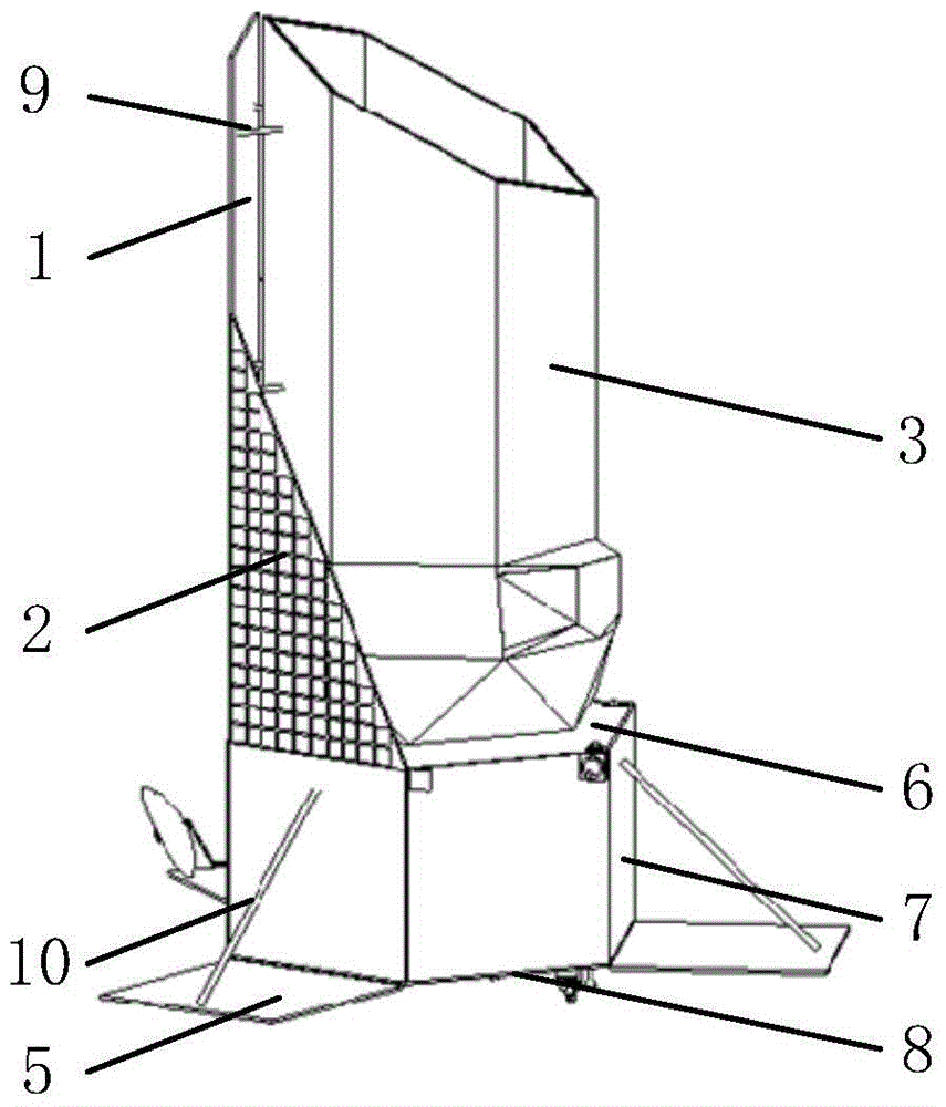
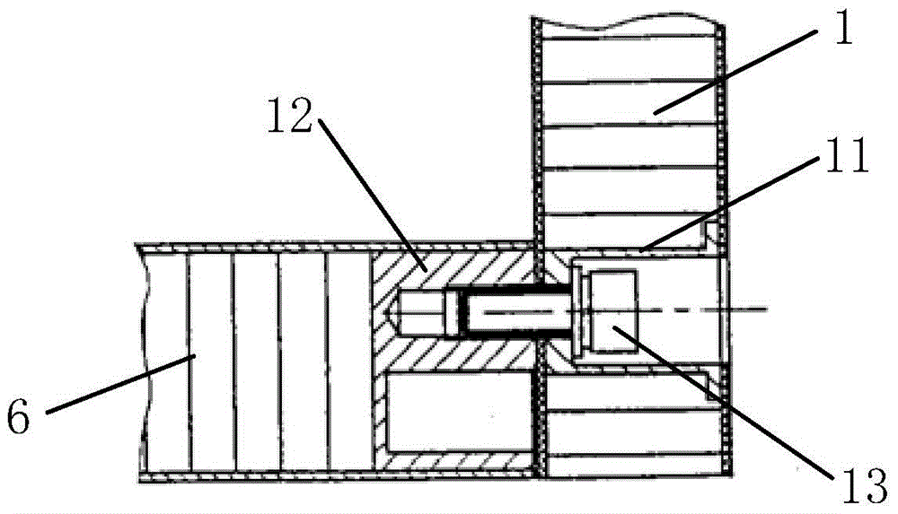
[0015] Such as Figure 1-3 As shown, the embodiment of the present invention provides a solar wing layout structure of a high-precision spacecraft, including a top solar wing main board 1, a top solar wing side plate 2, a payload 3, a spacecraft platform 4, a bottom solar wing 5, The platform top plate 6, the platform side plate 7, the platform bottom plate 8, the top solar wing pressing rod 9 and the bottom solar wing pressing rod 10; the top solar wing main board 1 and the top solar wing side pl...


PUM


Abstract

The invention discloses a solar wing layout structure of a high-precision spacecraft. A top solar wing main plate and top solar wing side plates form a top solar wing which is fixedly installed on a platform top plate through bolts; an included angle between the top solar wing main plate and each top solar wing side plate is 120 degrees; the section of a spacecraft platform is in the shape of a regular hexagon, the top solar wing main plate is rectangular, each top solar wing side plate is triangular, and a bottom solar wing is installed at the bottom of a platform bottom plate; top solar wing honeycomb sandwich embedded parts are pre-embedded in the top solar wing main plate and the top solar wing side plates, and platform top plate honeycomb sandwich embedded parts are pre-embedded in the platform top plate; and a top solar wing pressing rod is installed among the top solar wing main plate, the top solar wing side plates and a payload. The solar wing layout structure disclosed by the invention can effectively improve the connection stiffness between the solar wing and the spacecraft platform so as to reduce the micro-vibration of the solar wing and improve the attitude stability of the spacecraft platform, and has the advantages of simple configuration, convenient connection and obvious effect.

Description

technical field [0001] The invention relates to the field of spacecraft, in particular to a solar wing layout structure of a high-precision spacecraft, which can be applied to spacecraft with relatively high attitude stability. Background technique [0002] With the development of my country's spacecraft in the direction of high precision and high stability, the payloads carried by it have higher and higher requirements for the attitude stability of the platform. It is necessary to minimize the micro-vibration of the spacecraft platform to improve the attitude stability of the platform. [0003] One of the main sources of spacecraft microvibration is solar wing flexural vibration. The current spacecraft platform basically uses movable solar wings, and the connection stiffness with the platform is low. When the spacecraft performs orbit transfer or attitude adjustment, it will produce micro-vibration, thereby reducing the attitude stability of the platform. In addition, in o...

Claims


Application Information

Patent Timeline
Patent Type & Authority Patents(China)
IPC IPC(8): B64G1/44
CPCB64G1/44
Inventor 黄帆周益倩陈昌亚陈晓
Owner SHANGHAI SATELLITE ENG INST
Why Eureka
Try Eureka