
Threading apparatus for embroidery

A threading and embroidery technology, applied in the field of threading devices for embroidery, can solve the problems of insufficient safety, cumbersome threading, increased workload, etc., and achieve the effect of improving production effect, simple threading process, and reducing workload

Inactive Publication Date: 2016-04-13
樊秀英
View PDF1 Cites 4 Cited by
  • Summary
  • Abstract
  • Description
  • Claims
  • Application Information

AI Technical Summary

Problems solved by technology

[0004] With the development of embroidery machines, the number of heads and needles has increased greatly. The number of heads can reach the number of heads, and the number of needles can reach the number of needles. for cumbersome
The anti-slip sheet is easy to wear when the tension adjustment handle is constantly adjusted, and it cannot fix the thread take-up spring. When using this type of intermediate thread, it can only be equipped with a flat upper panel, resulting in most of the thread take-up rod being exposed outside. When the pole moves up and down, it is easy to cause injury to the operator and is not safe enough
The thread take-up spring is also exposed outside and is easy to be bent or broken when touched, resulting in damage to the intermediate thread and making it unusable
The tension adjustment handle rotates and adjusts the thread take-up springs of all stitches to go up and down together, but cannot be adjusted independently, resulting in the tension adjusted for the previous stitch not being applicable for the next stitch and readjusting, and returning to the previous stitch requires readjustment, which greatly increases Increased workload and affected the stability of embroidery work

Method used


Image

  • Threading apparatus for embroidery
  • Threading apparatus for embroidery
  • Threading apparatus for embroidery

Examples


Embodiment 1

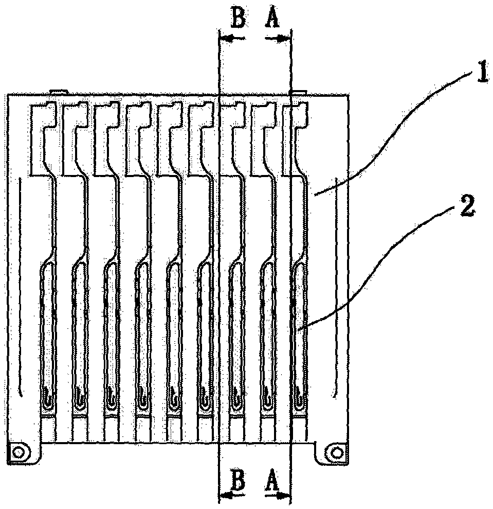
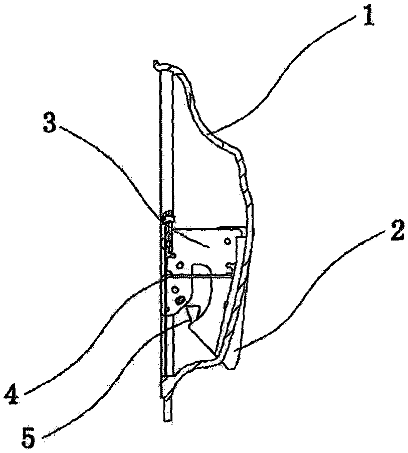
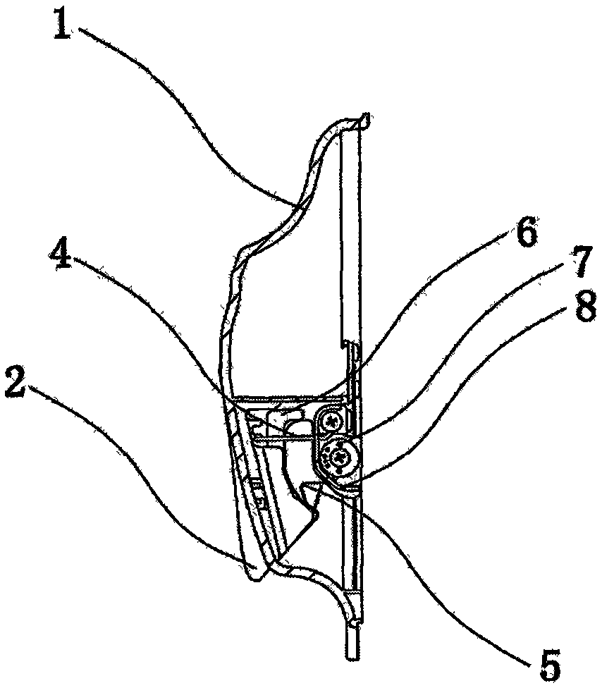
[0024] Embodiment 1: as image 3 , Figure 4 As shown, a thread passing device for embroidery includes a base 1. The base 1 is composed of a bottom plate and a panel. The middle part of the panel bulges outwards and its two ends are fixedly mounted on the bottom plate. A hollow cavity is formed between the two. Multiple sets of wire passing components are contained in the cavity. A fixed plate 9 and a line retaining plate 10 are installed on the inner surface of the base plate, and the line retaining plate 10 is installed between the base plate and the fixed plate 9 .

[0025] Such as Figure 4 and Figure 5 As shown, the wire passing assembly includes a holding plate 3 vertically installed on the fixing plate. The front end of the holding plate 3 is covered with a holding plate cover 2. The holding plate cover 2 extends out of the cavity from the panel and passes through the holding plate cover 2 of the panel. Thread grooves are reserved on both sides, that is, keep a cor...


PUM


Abstract

A disclosed threading apparatus for embroidery comprises a pedestal, the pedestal is composed of a bottom plate and a surface plate, the central section of the surface plate protrudes outwards, two sides of the surface plate are connected with the bottom plate, and a hollow chamber is formed between the surface plate and the bottom plate; the chamber is inside provided with multiple groups of threading assemblies, each threading assembly comprises a retaining plate perpendicularly arranged on the bottom plate, the front side of the retaining plate is guaranteed to stretch out of the chamber from the surface plate, and two sides, penetrating the surface plate, of the retaining plate are provided with a threading groove; and one lateral side of the retaining plate is provided with a tension regulator, the tension regulator is provided with a yarn take-up spring, and the yarn take-up spring possesses one torque spring end arranged on the tension regulator in a sleeving way, and one yarn take-up hook end extending out of the tension regulator. The whole threading apparatus is a cladding body, and all assemblies are wrapped in the pedestal, so that an operator is guaranteed to uneasily touch the threading-apparatus motion parts and part damage and personnel injury are avoided.

Description

technical field [0001] The invention relates to the technical field of thread passing devices for embroidery machines, in particular to a thread passing device for embroidery. Background technique [0002] The existing embroidery machine is more advanced in the middle thread. This structure is also used in the Chinese patent ZL200710070827. Columns and over-the-wire ceramics. [0003] The embroidery thread goes through the holes under the two rollers, then into the thread take-up spring, then returns to the hole under the rollers, passes through the thread take-up lever, and then passes through the thread-passing ceramics. The U-shaped seat is fixed on the upper panel, the tension adjustment handle adjusts the thread take-up spring to move up and down to increase the movement stroke of the thread take-up spring, and the anti-slip sheet is used to lock the thread take-up spring so that it cannot move. [0004] With the development of embroidery machines, the number of heads...

Claims


Application Information

Patent Timeline
IPC IPC(8): D05C11/10D05C11/08
Inventor 樊秀英
Owner 樊秀英
Learn More