Countertop Quick Mount Fittings for Faucets

A technology for installing devices and faucets, which is applied in water supply devices, indoor sanitary pipeline devices, buildings, etc., can solve the problems of poor shear resistance, time-consuming and laborious, and inconvenient installation, and achieve strong shear resistance, convenient operation, and compact effect

Active Publication Date: 2017-09-29
NINGBO AOLEISHI SANITARY WARE
View PDF1 Cites 13 Cited by
  • Summary
  • Abstract
  • Description
  • Claims
  • Application Information

AI Technical Summary

Problems solved by technology

This installation method that needs to be assembled and locked under the table is time-consuming and laborious for the faucet installers
Aiming at the above-mentioned shortcomings, there is a quick installation method for faucets on the market. The patent application number is US20120137427A1, which also discloses a solution for installing a faucet on the table. This solution has two screws and two locking parts. , however, the two screws occupy part of the space in the installation hole, resulting in a small space for passing through the water inlet pipe in the middle, so there is a great limitation on the size of the water inlet pipe
Furthermore, the width direction of the locking member will inevitably occupy part of the space of the installation hole, making the installation space smaller, which not only limits the size of the water inlet pipe of the faucet, but also is not convenient enough for installation, which is time-consuming and laborious.
And it is only supported by two screws with limited diameter, the strength of the faucet cannot be well guaranteed, and the shear resistance is also very poor
In the prior art, although there are products that use magnetic snap-in stops to achieve installation, the problem is that their reliability is relatively poor, the installation requirements are relatively high, and the cost is relatively high

Method used


Image

  • Countertop Quick Mount Fittings for Faucets
  • Countertop Quick Mount Fittings for Faucets
  • Countertop Quick Mount Fittings for Faucets

Examples


Embodiment Construction

[0018] The embodiments of the present invention will be further described below in conjunction with the drawings.

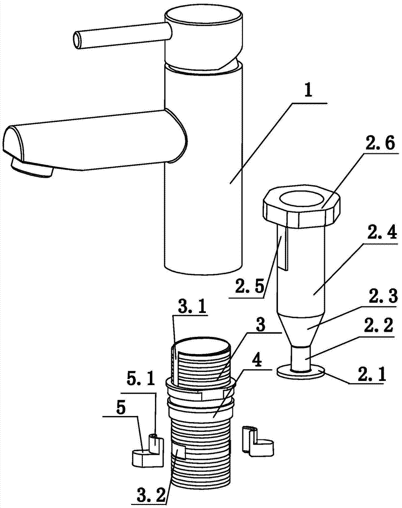
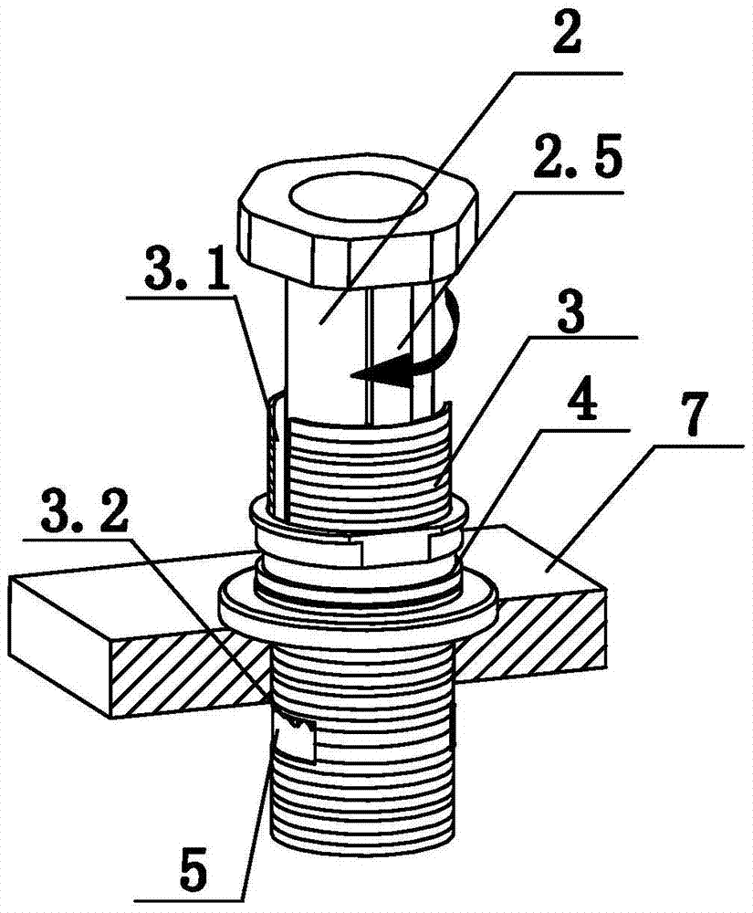
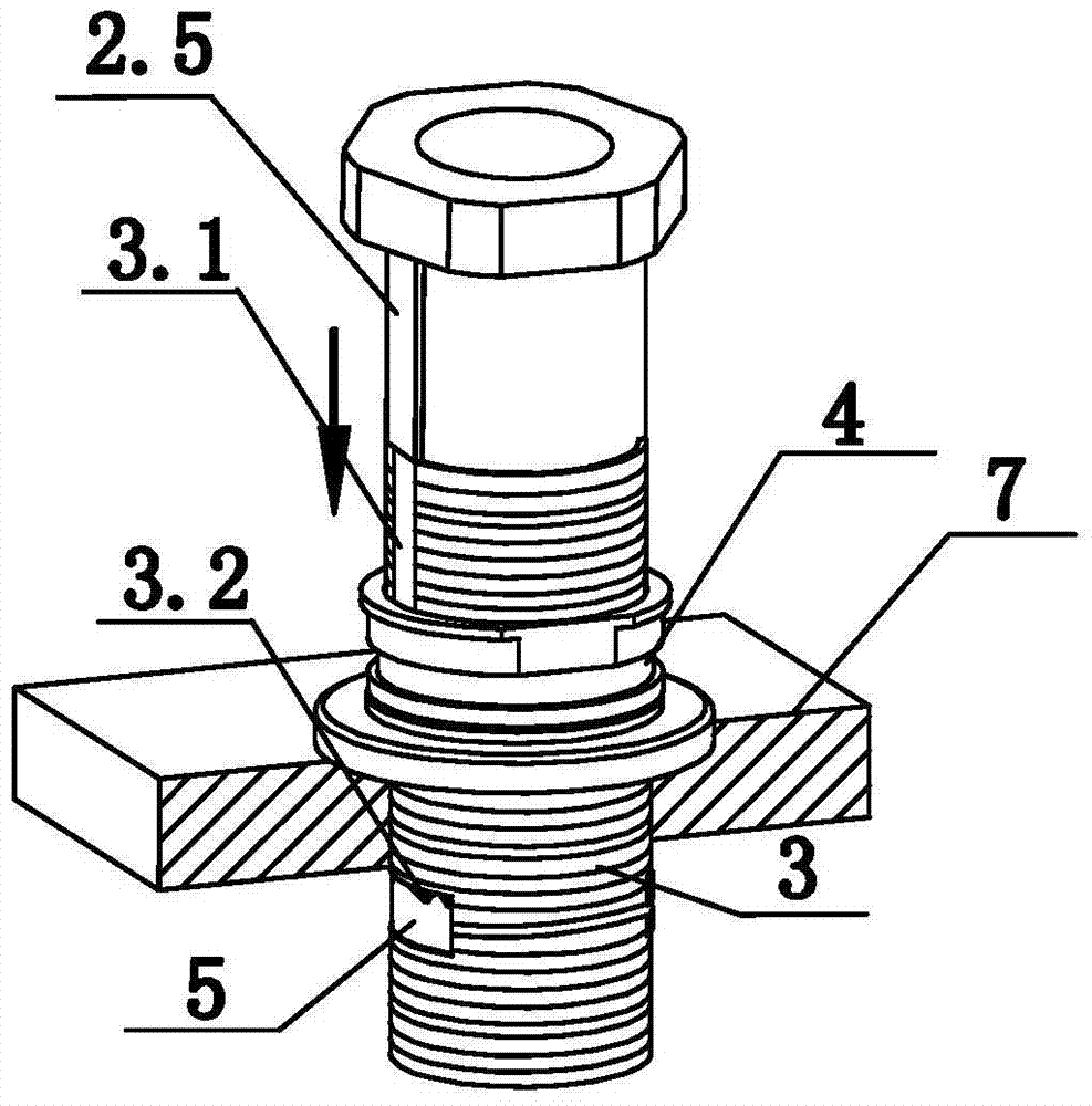
[0019] Such as Figure 1-11 As shown, an on-table quick installation device for faucets includes a faucet body 1 located above the table top 7, a screw sleeve 3 for installing the faucet body 1 in the mounting hole of the table top 7, and A mounting seat 4 that limits the axial displacement between the table 7 and the screw sleeve 3 and at least two sliding blocks 5, the mounting seat 4 is sleeved and connected to the outer periphery of the screw sleeve 3, and the screw At least two through holes 3.2 for the slider 5 to slide outward from the inner cavity of the screw sleeve 3 are provided on the outer periphery of the sleeve 3 at a position below the table 7 corresponding to the position, and it also includes a drive for driving the slider 5 to extend outward. The through hole 3.2 is used to realize the auxiliary installation tool 2 of the sliding block 5 in the ax...


PUM


Abstract

The invention discloses a table-board-type rapid mounting device for a faucet. The table-board-type rapid mounting device comprises a faucet body positioned above a table-board, a screw barrel mounted inside a mounting hole in the table-board in a sleeving manner for mounting the faucet body, as well as a mounting base and at least two sliders for limiting the axial displacement between the table-board and the screw barrel, wherein a mounting base is connected to the periphery of the screw barrel in a sleeving manner, the periphery of the screw barrel, corresponding to the lower part of the table-board, is provided with at least two through holes for the sliders to slide outwards from an inner cavity of the screw barrel, and the table-board-type rapid mounting device further comprises an auxiliary mounting tool for driving the sliders to extend out of the through holes so as to realize the axial limiting effect of the sliders; and the screw barrel is provided with a hollow inner cavity allowing the auxiliary mounting tool to slide inside so as to play the role of driving the sliders. With the adoption of the table-board-type rapid mounting device for the faucet, all the mounting work of the faucet can be carried out on the table-board rapidly and conveniently, and the axial limiting effect with the table-board is good.

Description

Technical field [0001] The invention relates to the field of faucet installation, in particular to an on-stage quick installation device for a faucet. Background technique [0002] The installation of conventional faucets is usually carried out under the countertop. Therefore, professionals need to bend over for a long time, or squat or lie under the dark and narrow basin, and use a variety of special tools to complete. This installation method that requires assembly and locking under the countertop is time-consuming and laborious for the faucet installer. In view of the above-mentioned shortcomings, a countertop quick installation method for faucets has appeared on the market. The application number is patent US20120137427A1. It also discloses a solution for installing a faucet on a countertop. The solution is equipped with two screws and two locking parts. However, the two screws occupy part of the space of the installation hole, resulting in a small space passing through the ...

Claims


Application Information

Patent Timeline
Patent Type & Authority Patents(China)
IPC IPC(8): E03C1/04
Inventor 张伟王勇汪家德张益儿
Owner NINGBO AOLEISHI SANITARY WARE
Why Eureka
Try Eureka