Structure-optimized drill rod on spiral drilling machine

A technology for auger drilling rigs and drill pipes, which is applied in the field of drill pipes with optimized structures on auger drilling rigs, which can solve problems such as easy wear, deformation of helical blades, and large soil friction, so as to reduce wear, increase anti-deformation strength, and strengthen strength Effect

Active Publication Date: 2016-04-13
XUZHOU SHENGHE WOOD
View PDF7 Cites 4 Cited by
  • Summary
  • Abstract
  • Description
  • Claims
  • Application Information

AI Technical Summary

Problems solved by technology

However, the front auger drilling machine is generally dry drilling, which is easy to cause deformation of the helical blade during dry drilling, and at the same time, the friction with the soil is large, and it is easier to wear

Method used


Image

  • Structure-optimized drill rod on spiral drilling machine
  • Structure-optimized drill rod on spiral drilling machine
  • Structure-optimized drill rod on spiral drilling machine

Examples


Embodiment

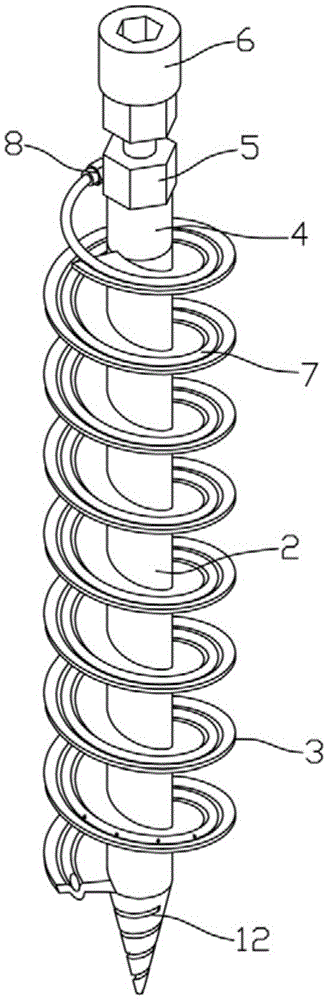
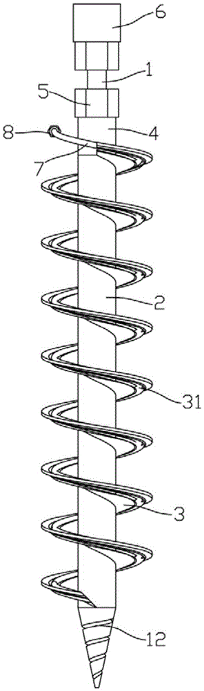
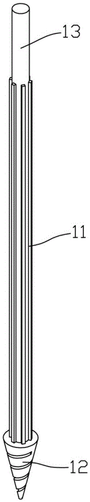
[0016] Example: see Figures 1 to 5 As shown, a drill rod with an optimized structure on an auger drill includes a rod body 1. The rod body 1 is composed of a spline shaft 11, a drill bit 12 and a stud 13. The drill bit 12 and the stud 13 are formed on the upper and lower sides of the spline shaft 11 respectively. end, the spline shaft 11 is plugged with a spline sleeve 2, and the outer wall of the spline sleeve 2 is welded and fixed with a helical blade 3. Spiral water delivery pipe 7 is welded in the tendon groove 31 of water delivery pipe 7, and the upper end of water delivery pipe 7 is fixedly connected with water pipe joint 8, and the lower end of water delivery pipe 7 is welded and fixed with spiral guide round rod 9, and guide round rod 9 is welded and fixed on the spiral In the tendon groove 31 of the blade 3 lower end, the bottom end of the guide round rod 9 and the bottom end of the helical blade 3 are formed with an inclined guide angle a, and several water outlet h...


PUM


Abstract

The invention discloses a structure-optimized drill rod on a spiral drilling machine. A rod body of the drill rod is composed of a spline shaft, a drill bit and a double-screw bolt. The drill bit and the double-screw bolt are formed at the upper end and the lower end of the spline shaft respectively. A spline sleeve is inserted into the spline shaft. A spiral blade is fixedly welded to the outer wall of the spline sleeve. A rib groove for extending a spiral line of the spiral blade is formed in the spiral blade. A spiral water conveying pipe is welded into the rib groove of the spiral blade. A water pipe joint is fixedly connected to the upper end of the water conveying pipe. A spiral guide round rod is fixedly welded to the lower end of the water conveying pipe and fixedly welded into the rib groove in the lower end of the spiral blade. Inclined guide angles are formed at the bottom end of the guide round rod and the bottom end of the spiral blade. A plurality of water outlet holes are formed in the wall of the lower end of the water conveying pipe. The spiral blade of an existing spiral drilling machine is modified, the rib groove is additionally formed to enhance strength of the spiral blade, the spiral blade is provided with an output pipe, the output pipe can be used when the spiral drilling machine sprays water, and abrasion to the spiral blade can be reduced.

Description

Technical field: [0001] The invention relates to the technical field of auger drilling machines, in particular to a drill rod with an optimized structure on the auger drilling machine. Background technique: [0002] Auger drilling machine, as the name suggests, is a drilling machine with helical blades, which is generally used for drilling on construction sites. When an auger drill is used, the cut soil is brought out of the bottom surface by the helical blades on the drill rod. However, the front auger drilling rig is generally dry drilling, and the helical blade is likely to be deformed during dry drilling, and at the same time, the friction with the soil is large, and it is easier to wear. Invention content: [0003] The object of the present invention is to aim at the deficiencies of the prior art, and provide a drill pipe with an optimized structure on the auger drilling machine. The hole is changed to wet drilling, which can reduce the wear of the screw blade. [...

Claims


Application Information

Patent Timeline
Patent Type & Authority Applications(China)
IPC IPC(8): E21B17/22E21B21/00
CPCE21B17/22E21B21/00
Inventor 杜福安
Owner XUZHOU SHENGHE WOOD
Why Eureka
Try Eureka