
High-pressure metal powder supply system based on pressure difference control

A metal powder and supply system technology, which is applied to the system field of supplying metal fuel powder to a metal engine, can solve the problems of reduced engine working efficiency, inability to work stably and continuously, and reduced metal powder concentration, and achieves the effect of improving working efficiency

Active Publication Date: 2016-04-13
HARBIN ENG UNIV
View PDF3 Cites 5 Cited by
  • Summary
  • Abstract
  • Description
  • Claims
  • Application Information

AI Technical Summary

Problems solved by technology

[0003] In the existing engine supply system, the metal fuel powder grain is cut by high-speed jet to supply the engine for combustion, such as patent CN102644932A. The biggest disadvantage of this supply method is that during the fuel supply process, the metal fuel powder will gradually The reduction will lead to a decrease in the concentration of metal powder in the fuel, and the working efficiency of the engine will also decrease with the reduction of the metal fuel powder, and it will not be able to continue to work stably
[0004] In the existing engine supply system, how to uniformly and stably supply metal fuel powder to the combustion chamber has not been well resolved. During the fuel supply process, as the metal powder gradually decreases, the concentration of the supplied metal powder will decrease, and the engine The work efficiency will also decrease with the decrease of the powder concentration and cannot work stably

Method used


Image

  • High-pressure metal powder supply system based on pressure difference control

Examples


Embodiment Construction

[0012] The present invention is described in more detail below in conjunction with accompanying drawing example:

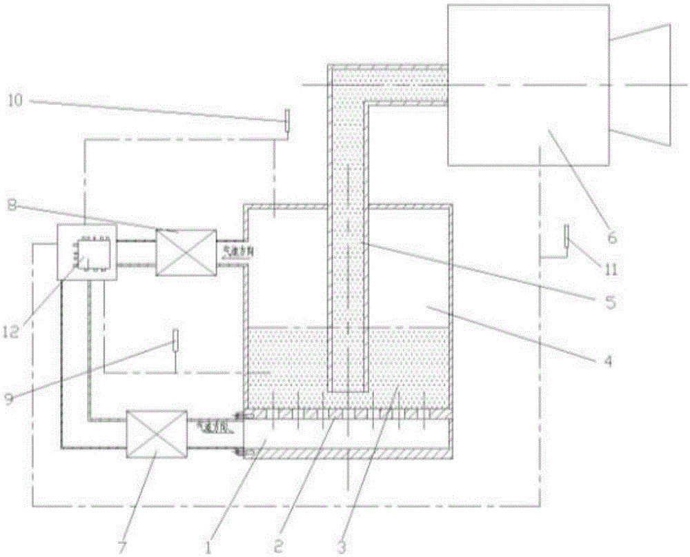
[0013] combine figure 1 , a metal powder high-pressure supply system based on differential pressure control in the present invention, an air inlet channel 1 is opened at the lower part of the medicine box, and an orifice plate 2 is arranged between it and the inside of the medicine box, and a metal powder 3 is installed above the orifice plate 2, Above the metal powder is air 4, and the metal powder is supplied into the combustion chamber 6 through the combustion chamber supply pipe 5, and an exhaust pipe is arranged on the top of the medicine box.

[0014] The air intake pipeline is provided with an air intake regulating valve 7, which is connected with the medicine box by a pipeline, and the exhaust pipeline is provided with an exhaust regulating valve 8, which is connected with the medicine box by a medicine box, respectively used to control the intake speed a...


PUM


Abstract

The invention aims at providing a high-pressure metal powder supply system based on pressure difference control. The system is suitable for a metal engine and can be used for stably supplying metal powder to a combustion chamber of the metal engine. Air passes a porous board to evenly blow metal powder, meanwhile, the air pressure of a metal powder region and the air pressure of an upper air region are monitored, the air pressure of the upper air region is controlled through a regulating valve on an exhausting pipeline, the pressure different of the upper portion and the lower portion is equal to 0.2 of the atmospheric pressure, and at this moment, the metal powder at the lower portion is blown by air to become gas-solid two-phase flow and is in a stable and even state. The metal powder obtained at this moment is supplied to the combustion chamber so that stable combustion in the combustion chamber can be guaranteed. A pressure sensor is arranged in the combustion chamber to monitor the pressure intensity in the combustion chamber, and it is kept that the pressure intensity in the combustion chamber is smaller than that of the metal powder region all the time. By the adoption of the high-pressure metal powder supply system, the better combustion state can be achieved and the work efficiency of the engine is improved.

Description

technical field [0001] The present invention relates to a metal engine, in particular to a system for supplying metal fuel powder to the metal engine. Background technique [0002] At present, underwater high-speed vehicles need to carry oxidizers themselves. The powder fuel supply device is a key part of a ramjet engine that uses high-energy-density metal-based fuel or metal powder as fuel. Considering the requirements for ignition in the combustion chamber, the powder supply device should provide powder that is uniform in steps and has a stable and reliable flow rate. flow. [0003] In the existing engine supply system, the metal fuel powder grain is cut by high-speed jet to supply the engine for combustion, such as patent CN102644932A. The biggest disadvantage of this supply method is that during the fuel supply process, the metal fuel powder will gradually The reduction will lead to a reduction in the concentration of metal powder in the fuel, and the working efficienc...

Claims


Application Information

Patent Timeline
IPC IPC(8): F02M21/12
CPCF02M21/12Y02T10/30
Inventor 刘平安常浩王良刘俊鹏邹高万于俊卫董惠
Owner HARBIN ENG UNIV
Learn More