Engine energy increasing system

A technology of engine and lubrication system, applied in the direction of charging system, internal combustion piston engine, engine components, etc., can solve the problem of high cost, achieve the effect of enhancing power, improving combustion efficiency, and increasing activity

Inactive Publication Date: 2016-04-13
吴国东
View PDF0 Cites 3 Cited by
  • Summary
  • Abstract
  • Description
  • Claims
  • Application Information

AI Technical Summary

Problems solved by technology

[0003] However, the effects of the above-mentioned engine boosting modes are not ideal, and the cost of implementation is relatively high

Method used


Image

  • Engine energy increasing system

Examples


Embodiment Construction

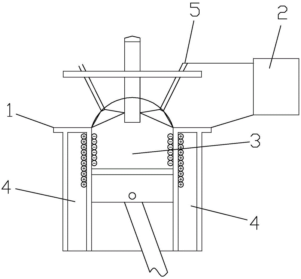
[0013] refer to figure 1 , a kind of engine booster system provided by the present embodiment, comprises engine 1, ion generator 2, and described engine 1 comprises combustion chamber 3, the air pipe 5 that communicates with combustion chamber 3 and the cooling cavity that surrounds combustion chamber 3 4. The ion generator 2 includes an A-type ion charge output module and a B-type ion charge output module, the output end of the A-type ion charge output module is connected to the air pipeline 5, and the output end of the B-type ion charge output module is connected to the cooling chamber 4 connections, the polarity of the ion charge output by the A-type ion charge output module is opposite to the polarity of the ion charge output by the B-type ion charge output module, and the A-type ion charge and B-type ion charge can be positive ions respectively Particles of opposite polarity to negative ions, positrons, and negative electrons. In order to control the output of ion charge...


PUM


Abstract

The invention discloses an engine energy increasing system which comprises an engine and an ion generator, wherein the engine comprises a combustion chamber, an air line communicating with the combustion chamber, and a cooling chamber surrounding the periphery of the combustion chamber; the ion generator comprises an A-type ionic charge output module and a B-type ionic charge output module; the output terminal of the A-type ionic charge output module is connected with the air line; the output terminal of the B-type ionic charge output module is connected with the cooling chamber; and the polarity of ionic charge output by the A-type ionic charge output module is opposite to the polarity of ionic charge output by the B-type ionic charge output module. According to the invention, a strong special ionic field can be formed outside the whole combustion chamber, the air line brings A-type ionic charge into the combustion chamber, and molecules of combustible mixture of the A-type ionic charge and B-type ionic charge attached to the cylinder wall of the combustion chamber of the engine merge with each other violently and quickly in extremely short time, so as to increase combustion vitality, thus improving the combustion efficiency of fuel oil.

Description

technical field [0001] The invention relates to an engine system, in particular to an engine booster system. Background technique [0002] At present, improving the power of the automobile system is mainly to increase the combustion efficiency of fuel, so as to save fuel and increase the power. The power of the automobile system can be improved mainly through the following methods: Method 1. High-flow air core replaces the filter , increase the air intake. Since the engine will generate various resistances during operation, the actual inhaled air volume does not meet the standard. Therefore, how to increase the intake air volume of the engine in the case of inconvenient exhaust volume has become the primary course for improving power input. . To increase the air intake of the engine is actually to reduce the resistance it generates during the process of inhaling air. Replace the filter with a high-flow air core or a mushroom head. Method 2: Replace the cylinder gasket or...

Claims


Application Information

Patent Timeline
Patent Type & Authority Applications(China)
IPC IPC(8): F02M27/04
CPCF02M27/042Y02T10/12
Inventor 吴国东陈国凡邓锦谊
Owner 吴国东
Why Eureka
Try Eureka