Waste heat coil of heating furnace

A heating furnace and waste heat technology, applied in tubular elements, heat exchange equipment, household stoves/stoves, etc., can solve problems such as limited flue space, affecting smoke exhaust effect, hindering flue gas circulation, etc., to achieve improved effect and beautiful appearance , the effect of extending the length

Inactive Publication Date: 2016-04-13
宜昌市家和现代农业机械有限公司
View PDF0 Cites 1 Cited by
  • Summary
  • Abstract
  • Description
  • Claims
  • Application Information

AI Technical Summary

Problems solved by technology

However, most of the existing waste heat pipes are placed in the flue in a spiral manner.
The problem is that due to the limited space of the flue, the spiral coil installed hinders the circulation of the flue gas
Affect the smoke exhaust effect

Method used


Image

  • Waste heat coil of heating furnace
  • Waste heat coil of heating furnace

Examples


Embodiment Construction

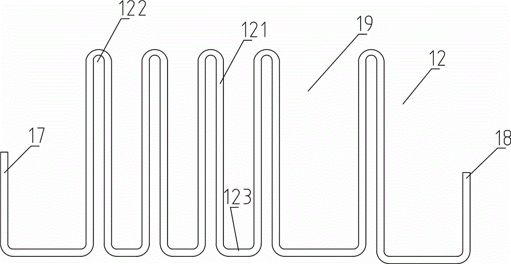
[0018] Such as figure 2 Among them, a waste heat coil for a heating furnace. The waste heat coil 12 is provided with a drain port 17 and a water inlet 18 at both ends. The middle section of the waste heat coil 12 is provided with a plurality of vertical bent pipes 121. Between each bending tube 121, a feeding gap 19 is arranged in parallel with each other. With this structure, it is convenient for the flue gas to pass between the vertical bent pipes 121, so that the structure reduces the obstruction to the flue gas. And this structure makes the water in the waste heat coil 12 warm up rapidly.

[0019] Such as figure 2 Among them, the length of the top connecting section 122 between each bent tube 121 is smaller than the length of the bottom connecting section 123 . Since the top connecting section 122 has a greater resistance to the flue gas, while the bottom connecting section 123 has almost no hindrance to the flue gas, the adoption of this structure further reduces the...


PUM


Abstract

The invention discloses a waste heat coil of a heating furnace. A water outlet and a water inlet are formed in the two ends of the waste heat coil. A plurality of vertical bent pipes are arranged in the middle section of the waste heat coil. The bent pipes are parallel to one another. A feeding notch is formed between every two adjacent bent pipes. The length of a top connection section between every two adjacent bent pipes is smaller than that of a bottom connection section. According to the waste heat coil of the heating furnace, by the adoption of the vertical bent pipe structure, the waste heat of smoke is sufficiently utilized, and influences on smoke ventilation are small; in addition, the appearance is attractive, and the waste heat coil can be combined with a flue conveniently; by the adoption of the structure, the length of the waste heat coil is effectively increased, so that heat in the smoke is sufficiently absorbed by the waste heat coil, and the temperature of hot water in the waste heat coil is also increased rapidly.

Description

technical field [0001] The invention relates to the field of components of civil heating furnaces, in particular to a heating furnace waste heat coil. Background technique [0002] In the existing heating furnace, the flue gas in the flue is discharged through the chimney, and the heat carried by the flue gas is also wasted. In the prior art, there is also a method of setting waste heat pipes in the flue to use the waste heat in the flue gas to heat the water in the pipes, thereby utilizing the waste heat of the flue gas. However, most of the existing waste heat pipes are placed in the flue in a spiral manner. The existing problem is that due to the limited space of the flue, the spiral coil installed hinders the circulation of the flue gas. Affect the smoke exhaust effect. Contents of the invention [0003] The technical problem to be solved by the present invention is to provide a heating furnace waste heat coil, which can make full use of the waste heat in the flue g...

Claims


Application Information

Patent Timeline
Patent Type & Authority Applications(China)
IPC IPC(8): F28F1/00F24B1/191
Inventor 谢华谢发鹏唐慧
Owner 宜昌市家和现代农业机械有限公司
Why Eureka
Try Eureka