A non-cohesive soil sampling device

A sampling device, non-cohesive soil technology, applied in the sampling device and other directions, can solve the problem that the baffle cannot be turned over, and achieve the effect of accurate sampling depth and improved accuracy

Active Publication Date: 2017-11-03
ANHUI UNIV OF SCI & TECH
View PDF1 Cites 0 Cited by
  • Summary
  • Abstract
  • Description
  • Claims
  • Application Information

AI Technical Summary

Problems solved by technology

[0004] First, the stopper is hinged to the inner wall of the sampling shovel. Since the sampling shovel is usually circular, the free end of the stopper that can be turned over is located at the diameter of the circular sampling shovel. Affected by the limiting effect of the arc-shaped side wall, the stopper actually The slice cannot be turned over to the inside of the sampling shovel;

Method used


Image

  • A non-cohesive soil sampling device
  • A non-cohesive soil sampling device
  • A non-cohesive soil sampling device

Examples


specific Embodiment 1

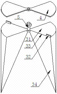
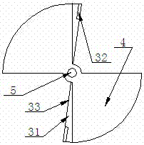
[0025] Such as Figure 1 to Figure 4 As shown, this is a schematic structural diagram of a non-cohesive soil sampling device according to this embodiment.

[0026] The non-cohesive soil sampling device described in this embodiment includes: a cylindrical sampling cylinder, the sampling cylinder includes a sampling top 1 and a sampling bottom 2 that are connected to each other by threads, and the sampling bottom 2 is provided with a fixed The baffle 4 and the movable baffle 3, the fixed baffle 4 is fixedly arranged on the inner wall of the sampling bottom 2, the movable baffle 3 is connected to the fixed baffle 4 through a central rotating shaft 5, and the movable baffle The piece 3 is located below the fixed baffle 4, the central rotating shaft 5 is arranged coaxially with the sampling cylinder, and the top surface of the movable baffle 3 is composed of two fan-shaped plates 31 symmetrical to the central rotating shaft 5 The arcs of the two sector plates 31 are both 90°, the str...

specific Embodiment 2

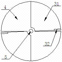
[0030] Such as Figure 5 As shown, this is a schematic structural diagram of a non-cohesive soil sampling device according to this embodiment.

[0031] In the non-cohesive soil sampling device described in this embodiment, there is one sampling middle part, and the rest of the structure is the same as that in the first embodiment.

[0032] When sampling, first rotate the movable baffle 3 so that the fixed baffle 4 and the movable baffle 3 are in position figure 2 As shown in the state, then by hammering the oblate washer 62 or pressing down the pressurizing handle 61 by manpower, the sampling cylinder is deepened to the sampling depth, while the soil sample entering the sampling cylinder is lifted up. The sampling indication baffle 7 and the limit guide post 71 are moved upward. The analysis and sampling personnel can observe the sampling depth in real time according to the scale on the surface of the limit guide post 71, and stop pressing down the sampling after reaching a predete...


PUM

PropertyMeasurementUnit
angleaaaaaaaaaa

Abstract

The invention discloses a cohesionless soil sampling apparatus. The apparatus comprises a cylindrical sampling cylinder, the sampling cylinder comprises a sampling top and a sampling bottom which are in threaded connection, the sampling bottom is provided with a fixed separation blade and a movable separation blade, the fixed separation blade is fixedly arranged on the inner wall of the sampling bottom, the movable separation blade is connected with the fixed separation blade through a center rotating shaft, the movable separation blade is positioned below the fixed separation blade, the center rotating shaft and the sampling cylinder are coaxially arranged, the top surface of the fixed separation blade is formed by two sector-shaped plates symmetrical to the center rotating shaft, the radian of each of the sector-shaped plates is 90DEG, the structure of the movable separation plate is same to the top surface of the fixed separation plate, and the top surface of the movable separation blade and the fixed separation blade are respectively vertical to the center rotating shaft. The bottom of the sampling cylinder can be conveniently closed without loss of a sampling amount, so the soil horizon sampling analysis working accuracy is improved.

Description

Technical field [0001] The invention relates to a non-cohesive soil sampling device, belonging to the technical field of sampling equipment for soft and low-cohesive soil layers. Background technique [0002] Fly ash and coal gangue solid waste produced during the operation of thermal power plants and coal mining are often used to fill coal mine subsidence areas, and the land is reclaimed after the surface is leveled. In order to understand the changes in the filling material of the subsidence area and the physical and chemical properties of the soil layer, it is necessary to conduct profile sampling, and then perform physical and chemical analysis based on the samples taken out by the sampling shovel. Because the filling layer of fly ash and coal gangue weathering material is relatively soft and has a small degree of adhesion, and the existing sampler has a simple structure, most of which have a bottom hinged closed structure. During the lifting process, the sample in the sample...

Claims


Application Information

Patent Timeline
Patent Type & Authority Patents(China)
IPC IPC(8): G01N1/08
CPCG01N1/08
Inventor 郑永红张治国胡友彪柳彦俊夏鸿宇
Owner ANHUI UNIV OF SCI & TECH
Why Eureka
Try Eureka