A Stamping Process Sequence Planning Method for Complex Sheet Metal Parts with Progressive Die

A technology of process sequence and sheet metal parts, which is applied in the field of stamping process sequence planning for complex sheet metal parts of progressive dies, and can solve problems such as unqualified product quality, mold rework, cumbersome calculations, etc.

Active Publication Date: 2018-05-22
盐城市金德模具制造有限公司
View PDF4 Cites 0 Cited by
  • Summary
  • Abstract
  • Description
  • Claims
  • Application Information

AI Technical Summary

Problems solved by technology

Lin and Sheu tried to combine the cascading method and exhaustive method to develop various possibilities, and then use various rules to select infeasible solutions and find all feasible solutions, but the calculation of this method is very cumbersome
[0007] Multi-station progressive die is a high-efficiency, high-precision, long-life stamping die. It is widely used in the fields of automotive structural parts, hardware appliances, and electronic instruments. Because the progressive die can be used in one stroke of the press As a result, it can significantly improve the utilization rate of machine tools, realize automatic production of products, reduce manual operations and reduce production safety risks. However, the use of multi-station progressive dies The parts to be processed have the characteristics of many processes and complex process design. The mold structure is generally very complicated, and the processes before and after are all related. There are many factors that need to be considered in the process of product, strip and mold design. Ignore Any small link may lead to unqualified product quality, mold repair or even complete scrapping, which greatly increases the difficulty of progressive die process and mold design, usually requires engineers with many years of experience in progressive die design Technicians are competent

Method used


Image

  • A Stamping Process Sequence Planning Method for Complex Sheet Metal Parts with Progressive Die
  • A Stamping Process Sequence Planning Method for Complex Sheet Metal Parts with Progressive Die
  • A Stamping Process Sequence Planning Method for Complex Sheet Metal Parts with Progressive Die

Examples


Embodiment

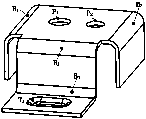
[0082] 1. Identify the features of sheet metal parts:

[0083] Typical features of sheet metal parts include punching, shearing, bending, stretching, local forming, etc., such as figure 1 The basic features of the sheet metal part shown are: 4 bending features B1, B2, B3, B4, 2 punching holes P1, P2, and 1 local forming feature T1.

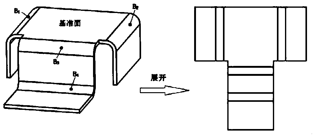
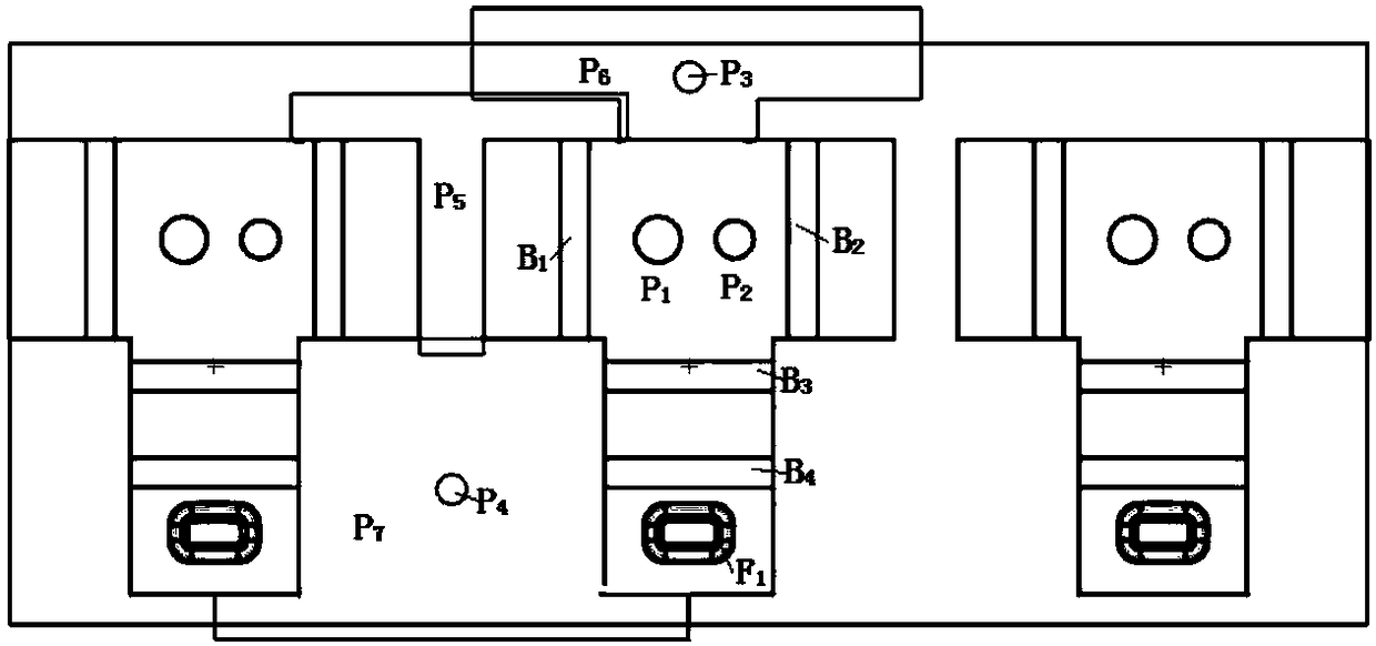
[0084] 2. Bending and unfolding, generating layout features:

[0085] refer to figure 2 As shown, the sheet metal parts are unfolded, laid out on the strip, and the waste design is carried out, among which punching type: punching P1, punching P2, punching P3, punching P4; blanking type: blanking P5, blanking Material P6, blanking P7; Bending type: Bending B1, Bending B2, Bending B3, Bending B4; Forming type: F1, the position of all features such as image 3 shown.

[0086] 3. Generate sequence planning matrix

[0087] According to the process layout rules, the operation priority order matrix is ​​generated, and different weights are defined o...


PUM


Abstract

The invention discloses a progressive die complex metal sheet member stamping process sequence planning method, comprising steps of performing metal plate characteristic identification, bending and expanding, generating a stock layout characteristic, and formulating a stock layout rule, listing all possible layout schemes by adopting a sequencing planning matrix, a synchronization sequence planning matrix, and an idle station planning matrix, listing all possible stock layout schemes, establishing an influence factor set U=[u1,u2,u3... un] and a corresponding weight set A=[w1,w2,w3, ...,wn], wherein w1+w2+w3+...+wn=1 and 0<=w1,w2,w3, ...,wn<=1, and calculating the multi-norm decision total score Ev sigma(j=i)<n>wjuj=w1*u1+w2*u2+w3*u3...wn*un according to the influence factor and the corresponding weight, wherein when the Ev value is the maximum, the scheme is optimal. The invention is simple and can obtain the optimal scheme through the data, can manufacture the correct working station stock layout without the stamping and processing knowledge and experience of the design personnel, gets rid of the designer, realizes the intelligent designing in a real meaning, and realizes the processing of the standardization production.

Description

technical field [0001] The invention relates to a method for planning a process sequence, in particular to a method for planning a process sequence for punching complex sheet metal parts of a progressive die. Background technique [0002] Since the 1970s, the research on computer-aided stamping process planning has begun. Schaffer (1971) and Nakahara et al. (1978) may be the first to study the problem of strip planning and continuous die design. They mainly use CAD / CAM technology to To solve the problem of stamping die design automation, there have been more researches on combining other methods in the CAD / CAM environment, such as Bergstrom et al. ) using knowledge base rules to obtain certain effects. In terms of commercial software, Pro / ENGINEER's Pro / SHEETMETAL, NX Progressive Die Wizard, etc. all provide better user interfaces, but they are still not widely applicable to automatic reasoning and layout of stamping parts with typical characteristics, punch division and co...

Claims


Application Information

Patent Timeline
Patent Type & Authority Patents(China)
IPC IPC(8): G05B19/4097
CPCG05B19/4097
Inventor 夏建生窦沙沙袁斌刘军张红蕾张本国
Owner 盐城市金德模具制造有限公司
Why Eureka
Try Eureka