Heat pump type curing barn environment humidity control system

A technology of environmental humidity and control system, applied in control/regulation system, non-electric variable control, simultaneous control of multiple variables, etc., can solve problems such as heat pump can not continue to work, heat conduction steel pipe frosting, unsafe and so on

Inactive Publication Date: 2016-04-13
HENAN BAIHENG ENERGY SAVING TECH
View PDF4 Cites 1 Cited by
  • Summary
  • Abstract
  • Description
  • Claims
  • Application Information

AI Technical Summary

Problems solved by technology

[0002] In the drying process of existing agricultural products, room type dryers, mesh belt dryers, etc. are used. The disadvantages are: first, it is unsafe and consumes a lot of energy. In order to overcome the above defects, most of my country has adopted heat pumps as heat sources in recent years. However, when the heat pump is used in a low-temperature environment (such as winter in northern my country, the thermal efficiency will be greatly reduced, and the key components of the heat pump such as the compressor and the heat-conducting steel pipe will frost, which will cause the heat pump to fail to continue to work.

Method used


Image

  • Heat pump type curing barn environment humidity control system
  • Heat pump type curing barn environment humidity control system
  • Heat pump type curing barn environment humidity control system

Examples


Embodiment Construction

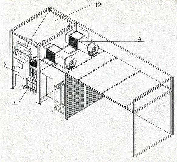
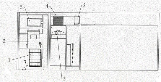
[0012] This technical solution is based on the exhaust gas recycling structure. See figure 1 , 2 , 3, and the electrical automatic control system (such as Figure 4 Shown).

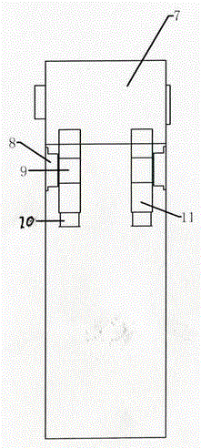
[0013] The technical solution is composed of a roasting barn and a heat pump unit room. The heat pump unit room 7 is provided with a heat pump unit 1, a circulating fan 2, a dehumidification fan 3, an electrical control cabinet 6 and a heat exchanger 9 with air intake and dehumidification. The heat pump unit room is a fully enclosed room, and an exhaust air duct 12 is laid above the heat pump unit room, and an exhaust air door 5 is installed on the port of the exhaust air duct. The moisture exhaust duct 11 is introduced into the exhaust air duct between the heat pump units. The moisture exhaust air duct is equipped with a moisture exhaust damper 10, and the moisture exhaust duct is located in the circulating return air duct on the upper part of the roasting barn to prevent the heat pump unit The external air...


PUM


Abstract

The invention discloses a heat pump type curing barn environment humidity control system. The heat pump type curing barn environment humidity control system comprises a heat pump unit, a circulation fan, a moisture exhausting fan, an electric control cabinet and a heat exchanger with an air feeding and moisture exhausting function which are arranged in a heat pump unit room; an air exhausting duct is laid above the heat pump unit room; an end opening of the air exhausting duct is provided with an air exhausting door; moisture exhausting high-temperature waste gas in a curing barn is led into the air exhausting duct of the heat pump unit room through a moisture exhausting duct; the moisture exhausting duct is provided with a moisture exhausting door; the moisture exhausting duct is located in a circulation return air duct at the upper part of the curing barn; one end opening of the air exhausting duct is provided with an air exhausting door; a fresh air ventilation duct is located in the circulation return air duct at the upper part of the curing barn; one end of the fresh air ventilation duct is communicated with the outside through a fresh air ventilation door; the other end of the fresh air ventilation duct intersects with the moisture exhausting duct in the curing barn; the intersection of the moisture exhausting duct and the fresh air ventilation duct is provided with a fresh fed air and moisture exhausted air heat exchanger; and a temperature sensor and a humidity sensor are arranged in the heat pump unit room.

Description

Technical field: [0001] The invention relates to a drying system suitable for drying agricultural products, which utilizes waste heat circulation to improve thermal efficiency. Background technique: [0002] Existing agricultural products use room dryers and mesh belt dryers in the drying process. The shortcomings are that they are unsafe and consume a lot of energy. In order to overcome the above shortcomings, in recent years, most of my country has adopted heat pumps as heat sources. However, when the heat pump is used in a low temperature environment (such as in winter in northern my country, the thermal efficiency will be greatly reduced, and the key components of the heat pump such as the compressor and the heat-conducting steel pipe will be frosted, causing the heat pump to fail to continue working. Summary of the invention: [0003] The task of the present invention is to provide a drying system that can ensure the use of high-temperature and high-humidity exhaust gas discha...

Claims


Application Information

Patent Timeline
Patent Type & Authority Applications(China)
IPC IPC(8): G05D27/02
CPCG05D27/02
Inventor 程烨朱景申李童张绍勇张二宾杨德亮都洪阳刘艳
Owner HENAN BAIHENG ENERGY SAVING TECH
Why Eureka
Try Eureka