
Independently-driven untwisting mechanism for cabling machine

A technology of independent driving and back-twisting mechanism, applied in cable/conductor manufacturing, electrical components, circuits, etc., can solve the problems of difficult processing and assembly, easy damage, complex structure, etc., to achieve simple operation, reasonable structure, and simplified structure. Effect

Inactive Publication Date: 2016-04-13
WUHU ELECTROTECHN MACHINERY
View PDF4 Cites 3 Cited by
  • Summary
  • Abstract
  • Description
  • Claims
  • Application Information

AI Technical Summary

Problems solved by technology

The technical defect of the four-bar linkage back-twist mechanism is that each wire reel frame must lead out a torsion shaft, and the torsion shaft at the position of the second gear pay-off reel is long and easily damaged; and this mechanism can only be used for two Segment cage
The gear back-twist mechanism works together through a large number of gear sets, and the structure is complex, which makes processing and assembly difficult
The traditional back-twist mechanism switches between full back-twist or non-back-twist, and the function conversion must be completed by the mechanic disassembling and assembling parts.

Method used


Image

  • Independently-driven untwisting mechanism for cabling machine
  • Independently-driven untwisting mechanism for cabling machine

Examples


Embodiment Construction

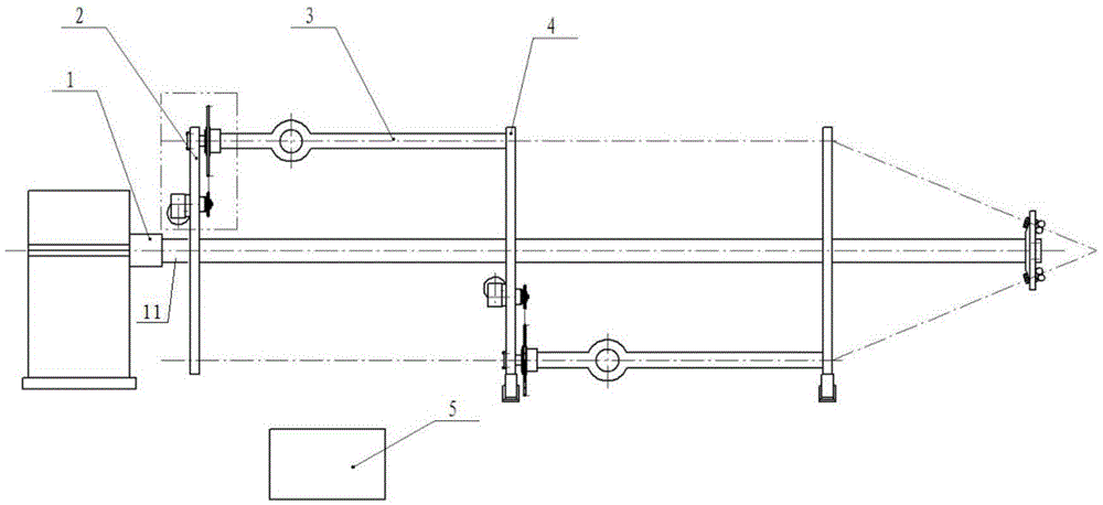
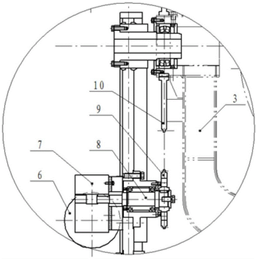
[0012] see figure 1 , 2 , an independently driven twist-back mechanism used on a cable forming machine, including a brush ring 1, an electric control system 5, front and rear capstans 2, 4 and a wire reel rotatably installed between the front and rear capstans 2, 4 The frame 3, the brush ring 1 includes slip rings and electric brushes, the outer side of the front winch 2 is equipped with a twist-back motor 6, and the inner side of the front winch 2 is rotated with a transmission shaft 8, and the twist-back motor 6 is connected to the transmission shaft 8. Drive shaft 8 is equipped with driving wheel 9, and one end of wire reel frame 3 is equipped with driven wheel 10, and driving wheel 9 is connected with driven wheel 10 transmission; And be electrically connected with electric control system 5, and electric brush is installed on the front capstan 2, and is electrically connected with back twisting motor 6.

[0013] In the present invention, the untwisting motor 6 is connect...


PUM


Abstract

The invention discloses an independently-driven untwisting mechanism for a cabling machine. The independently-driven untwisting mechanism comprises an electric brush ring, an electric control system, a front winch, a back winch and a winch frame rotationally mounted between the front winch and the back winch, wherein the electric brush ring comprises a slip ring and an electric brush; an untwisting motor is mounted on the outer side of the front winch; a transmission shaft is rotationally mounted on the inner side of the front winch; the untwisting motor and the transmission shaft are in transmission connection; a driving wheel is mounted on the transmission shaft; a driven wheel is mounted at one end of the winch frame; the driving wheel and the driven wheel are in transmission connection; the slip ring is arranged on a rotating shaft of the front winch and the back winch in a sleeving manner, and electrically connected with the electric control system; and the electric brush is mounted on the front winch and electrically connected with the untwisting motor. The independently-driven untwisting mechanism is reasonable in structure; the whole set of the untwisting mechanism is separated from the power for driving the winches to rotate; the rotating speed of the untwisting motor is adjusted through electric control to enable the rotating speed of the winch frame to be matched with the rotating speed of the winches, so that the technological requirements of complete untwisting, over-untwisting, insufficient untwisting and non-untwisting can be satisfied; and in addition, the independently-driven untwisting mechanism is simplified in structure, multifunctional, and simple and convenient to operate.

Description

technical field [0001] The invention relates to the field of components of a cable forming machine, in particular to an independently driven untwisting mechanism used on a cable forming machine. Background technique [0002] Cable forming machine equipment is a kind of mechanical equipment for twisting wire and cable. During the stranding process, in order to keep the wire reel frame on the stranding body level and meet the technological requirements of complete untwisting, it is necessary to configure an untwisting mechanism on the side of the cage. There are two kinds of back-twist mechanisms commonly used in cabling machines, namely: four-link back-twist mechanism and gear back-twist mechanism. The technical defect of the four-bar linkage back-twist mechanism is that each wire reel rack must lead out a torsion shaft, and the torsion shaft at the position of the second gear pay-off reel is long and easily damaged; and this mechanism can only be used for two The cage fram...

Claims


Application Information

Patent Timeline
IPC IPC(8): H01B13/02
CPCH01B13/0207
Inventor 王钟陶伟伟张士光孙健周璇德张登坪吴旭东曾俊梅
Owner WUHU ELECTROTECHN MACHINERY
Learn More