
Microgrid real-time voltage control method considering micro power source reactive output balance degree

A real-time voltage and control method technology, applied in the direction of AC network voltage adjustment, reactive power compensation, emergency treatment AC circuit layout, etc., can solve the problem of high investment in reactive power adjustment equipment, no consideration of reactive power injection, and safe and stable operation of microgrids Issues such as inability to obtain effective guarantees

Active Publication Date: 2016-04-13
XI AN JIAOTONG UNIV
View PDF2 Cites 11 Cited by
  • Summary
  • Abstract
  • Description
  • Claims
  • Application Information

AI Technical Summary

Problems solved by technology

However, the existing real-time voltage control methods do not consider the injected reactive power, the safe and stable operation of the microgrid cannot be effectively guaranteed, and the investment in reactive power adjustment equipment in the microgrid is relatively high.

Method used


Image

  • Microgrid real-time voltage control method considering micro power source reactive output balance degree
  • Microgrid real-time voltage control method considering micro power source reactive output balance degree
  • Microgrid real-time voltage control method considering micro power source reactive output balance degree

Examples


Embodiment Construction

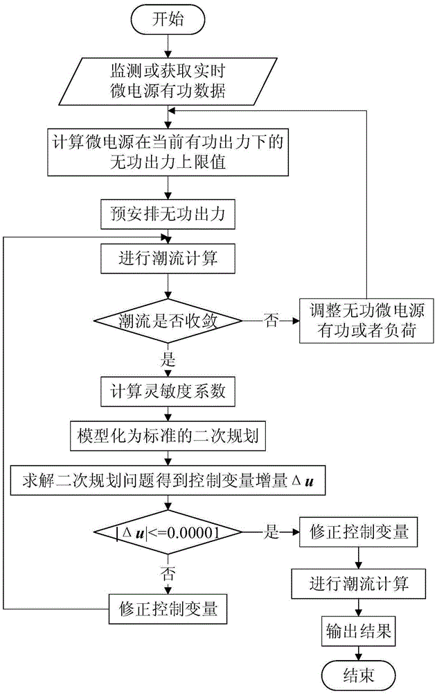
[0083] The present invention considers the micro-grid real-time voltage control method of the reactive power output balance degree of the micro-power supply, which specifically includes the following steps:

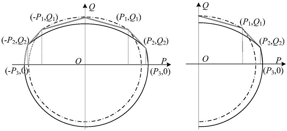
[0084] Step 1: For different types of micro-power sources, a general model of the upper limit of reactive power output of micro-power sources under different working conditions is established, including the following steps:

[0085] Step 1.1: Analysis of the operating characteristics of the micropower supply. According to the grid-connected form of the micro-power source in the micro-grid, it is divided into a direct grid-connected micro-power source and an inverter-interfaced micro-power source. The former mainly includes diesel generators and large grid equivalent power sources connected to the point of public coupling (PCC point). Those mainly include micro-gas turbines, fuel cells, wind turbines, photovoltaics and other micro-power sources, as well as batteries and s...


PUM


Abstract

The invention relates to a microgrid real-time voltage control method considering micro power source reactive output balance degree. The microgrid real-time voltage control method comprises the steps of establishing a piecewise linear mathematic model at the micro power reactive output upper limit for a universal inverter interface; by considering the micro power source reactive output balance degree, enabling all micro power sources in the microgrid to keep certain adjusting margin so as to better suit voltage deviations caused by random fluctuations of wind power, photo-electricity and load in the micro power sources so as to establish an operating restraint reactive optimized mathematical model including alternating current power flow, node voltage upper and lower limits, and micro power source reactive output upper and lower limits and the like; taking the micro power source reactive output as the control variable and taking the node voltage as the state variable; performing linear approximation on stable running points of an alternating current power flow constraint equation in a system based on a sensitivity relation; removing the state variable from the optimized model; and converting the non-convexity optimizing problem into a series of standard secondary planning sub problems for realizing rapid solving for the model, so that requirement on solving rapidness by real-time control is satisfied.

Description

【Technical field】 [0001] The invention relates to the field of operation control of micro-power sources in a micro-grid system, in particular to a real-time voltage control method for micro-grids considering the balance of reactive power output of micro-power sources. 【Background technique】 [0002] As an effective organizational form that makes full use of distributed clean energy for power production, microgrid has a good development prospect under the current severe situation of energy crisis and environmental problems. Compared with the large power grid, the load, wind power and photovoltaic distributed power in the micro-grid have greater volatility, which poses a huge challenge to the stable operation of the micro-grid, especially the problem of voltage stability, and requires a complete set of energy The management system realizes orderly management of distributed power sources and loads in the microgrid to maintain the long-term safe and stable operation of the micro...

Claims


Application Information

Patent Timeline
IPC IPC(8): H02J3/16
CPCH02J3/16H02J3/001Y02E40/30
Inventor 王建学罗南星张忠
Owner XI AN JIAOTONG UNIV
Learn More