
Servo motor with inertia disc and its installation method

A technology of servo motors and inertia discs, applied in the field of servo motors, can solve the problems of time-consuming and labor-intensive, cost-increasing, inflexible and inconvenient inertia adjustment, etc., and achieve the effects of cost reduction, convenient installation, and flexible and convenient inertia adjustment

Active Publication Date: 2017-10-31
安吉桢正运动控制技术有限公司
View PDF6 Cites 0 Cited by
  • Summary
  • Abstract
  • Description
  • Claims
  • Application Information

AI Technical Summary

Problems solved by technology

[0003] The invention mainly solves the technical problem that the change of the inertia of the original motor is achieved by changing the diameter of the rotor. Once the rotor is formed, the inertia is fixed and cannot be changed. The inertia adjustment is neither flexible nor convenient, which is very time-consuming and labor-intensive, and also increases the technical problem of cost. ;Provide a servo motor with an inertia disk, the rotor inertia can be adjusted by changing the size of the inertia disk, the inertia adjustment is flexible and convenient, it saves time and effort, and also reduces the cost, and there is no need to redesign the motor, and it will not affect the motor. The electromagnetic scheme and the overall structure are changed, so the motor has better stability and reliability

Method used


Image

  • Servo motor with inertia disc and its installation method
  • Servo motor with inertia disc and its installation method
  • Servo motor with inertia disc and its installation method

Examples


Embodiment

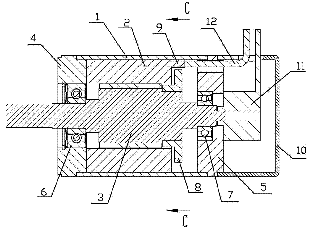
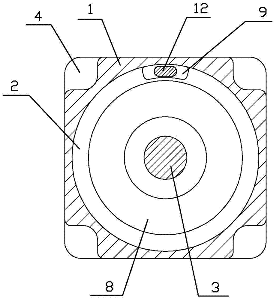
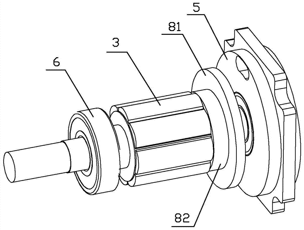
[0026] Embodiment: the servomotor of the band inertia disc of the present embodiment, as figure 1 , figure 2 , Figure 4 As shown, it includes a housing 1 and a stator 2 and a rotor 3 installed in the housing 1. The front end of the housing 1 is connected with a front end cover 4, and the rear end of the housing 1 is connected with a rear end cover 5. The front end cover 4 and the rotor A front bearing 6 is installed between the front ends of the rotor 3, a rear bearing 7 is installed between the rear end cover 5 and the rear end of the rotor 3, the stator 2 is filled with potting glue, and the potting glue surrounds the stator 2 to become a potting stator. There is a wire fixing body formed by filling glue protruding from the rear end surface of the glue stator. The wire 12 is embedded in the strip-shaped protrusion 9 and passes through the strip-shaped protrusion 9 and passes through the rear end cover 5 to lead out of the end cover. An inertia disk 8 is connected to the...


PUM


Abstract

The invention relates to a servo motor with an inertia disk and an installation method thereof. The servo motor with an inertia disk includes a housing, a stator and a rotor. There are front and rear end covers at the front and rear ends of the housing. An inertia disk is installed on the rotor. The inertia disk is located between the stator and the rear end cover. The stator fills Filled with sealing glue to become the glue-filled stator, the rear end surface of the glue-filled stator protrudes from the back end surface of the glue-filled stator to form a wire fixing body. between the body and the inertia disk. The installation method is as follows: first install the front bearing, rotor, inertia plate, rear bearing and rear end cover to form component A, then install the shell, stator and front end cover and then pour glue to form component B. Put the rear end into component B, and then install the encoder and the rear cover. The invention can conveniently increase the inertia of the motor to drive large loads, can flexibly adjust the size of the inertia, saves time and labor, reduces costs, and is simple to assemble and install.

Description

technical field [0001] The invention relates to a servo motor, in particular to a servo motor with an inertia disk which is convenient to adjust the inertia and simple to assemble and an installation method thereof. Background technique [0002] In the application of servo motors, the matching of motor inertia is involved. Because in the case of large load inertia, the use of low inertia motors cannot meet the requirements, so it is necessary to select a servo motor with corresponding inertia according to the load inertia. The traditional way to change the inertia is to redesign a motor and increase the rotor inertia by increasing the diameter of the rotor, but this method will cause a complete change in the electromagnetic scheme and structure of the motor, and once the rotor is formed, the inertia is fixed and cannot be done. If it needs to be changed, the motor must be redesigned, which cannot be adjusted flexibly, which is time-consuming and laborious, and increases the ...

Claims


Application Information

Patent Timeline
Patent Type & Authority Patents(China)
IPC IPC(8): H02K7/02H02K15/00
CPCY02E60/16
Inventor 金国华江思敏叶鹏林海齐玙珂李星星
Owner 安吉桢正运动控制技术有限公司
Learn More