
Stepping motor vibration reduction rotor

A technology of stepping motors and rotors, which is applied in the direction of electric components, electrical components, electromechanical devices, etc., can solve the problems of poor running stability of motors, and achieve the effect of reducing self-vibration and increasing stability

Pending Publication Date: 2022-02-08
SHANGHAI MOONS ELECTRICAL APPLIANCE
View PDF0 Cites 0 Cited by
  • Summary
  • Abstract
  • Description
  • Claims
  • Application Information

AI Technical Summary

Problems solved by technology

[0003] When the stepper motor is running, the rotor of the above-mentioned existing motor has radial and axial vibrations, and the running stability of the motor is very poor

Method used


Image

  • Stepping motor vibration reduction rotor
  • Stepping motor vibration reduction rotor
  • Stepping motor vibration reduction rotor

Examples


Embodiment Construction

[0035] Below in conjunction with the accompanying drawings of the present invention in embodiments, the technical solutions in the embodiments of the present invention are clearly and completely described, obviously, the described embodiments are part of the embodiments of the present invention rather than all embodiments. Based on the embodiments of the present invention, all other embodiments of ordinary skill in the art without creative efforts shall, should fall within the scope of the present invention.

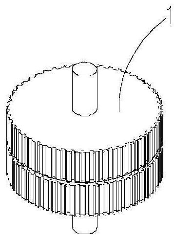
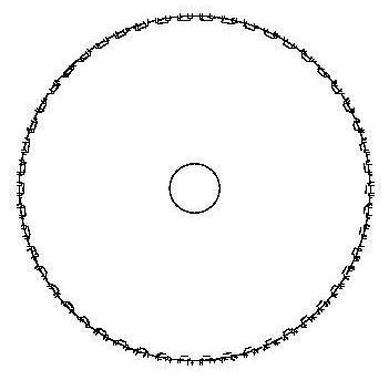
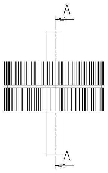
[0036] like Figure 6-9 As shown in A vibration stepping motor rotor comprising a rotor shaft 6, the front outer rotor core 7, the outer rotor core 8, the front inner rotor core 9, after the inner rotor core 10, the front side rotor core magnet 11, the rear side of the rotor core 12 magnet assembly 13 and the annular elastic body; said rotor shaft 6 sequentially into the front outer rotor core 7, front inner rotor core 9, elastomeric ring assembly 13, after the inner rotor co...


PUM


Abstract

The invention relates to a stepping motor vibration reduction rotor. The stepping motor vibration reduction rotor comprises a rotor shaft, a front outer side rotor core, a rear outer side rotor core, a front inner side rotor core, a rear inner side rotor core, front side rotor core magnetic steel, rear side rotor core magnetic steel and a circular ring elastic body assembly; the rotor shaft sequentially penetrates through the front outer side rotor core, the front inner side rotor core, the circular ring elastic body assembly, the rear inner side rotor core and the rear outer side rotor core; the front outer side rotor core and the front inner side rotor core form a front rotor core set, and the front side rotor core magnetic steel is arranged in a groove of the front rotor core set; and the rear outer side rotor core and the rear inner side rotor core form a rear rotor iron core set, and the rear side rotor core magnetic steel is arranged in a groove of the rear rotor core set. Compared with the prior art, the rotor can reduce the vibration of the motor and improve the running stability of the motor.

Description

Technical field [0001] The present invention relates to a stepping motor, particularly to a stepping motor rotor vibration. Background technique [0002] like Figure 1-5 , The conventional stepping motor rotor assembly, is composed of the conventional front and rear rotor core 3, the conventional magnet between two rotor cores 4 and the conventional motor shaft 2, the conventional front and rear rotor core 3 radially deflects a certain angle, the material 4 is generally conventional magnet NdFeB NdFeB. [0003] Stepper motor is running, the presence of the above-described conventional motor rotor radial and axial vibrations, poor motor running smoothly. Inventive content [0004] The object of the present invention is to solve the problems of the prior art described above and to provide a stepping motor rotor vibration. [0005] The object of the present invention can be achieved by the following technical solutions: [0006] According to one aspect of the present invention, the...

Claims


Application Information

Patent Timeline
Patent Type & Authority Applications(China)
IPC IPC(8): H02K37/10H02K1/27H02K1/2706H02K1/278H02K1/28H02K1/02H02K5/24
CPCH02K37/10H02K1/27H02K1/2706H02K1/278H02K1/28H02K1/02H02K5/24
Inventor 彭光明甘建军金万兵
Owner SHANGHAI MOONS ELECTRICAL APPLIANCE
Learn More