
Novel turbine acting device

A technology of power and turbine, applied in the direction of blade support components, stators, engine components, etc., can solve the problems of high manufacturing cost, reduced rigidity of wheel axle, high fuel consumption, etc.

Pending Publication Date: 2021-05-11
于洁
View PDF0 Cites 0 Cited by
  • Summary
  • Abstract
  • Description
  • Claims
  • Application Information

AI Technical Summary

Problems solved by technology

[0002] In the prior art, the prior art closest to this application is the working turbine technology on the turbine engine. Although the turbine engine in the prior art is called the crown in the industry, it belongs to the tip of the tip in the industry, but There are still design flaws, that is, the multi-stage power turbines in the turbine engine are all axially arranged, and the rotating speeds of the power impellers at all levels are basically the same when doing work, and even the diameter of the end power impeller is larger than that of the beginning power impeller. That is to say, in the prior art, the tip speed of the working impeller at the end of the turbine engine is greater than the tip speed of the working impeller at the beginning, so that the flow velocity of the working medium at the end, that is, the high-energy gas, will be equal to or lower than the tip speed of the working impeller at the end , which is the root cause of low efficiency and high fuel consumption at medium and low speeds, and the fact that the axial length is too large to reduce the rigidity of the axle and the manufacturing cost is high, which is not suitable for ordinary civilian industrial fields. This is the deficiency of the existing technology.

Method used


Image

  • Novel turbine acting device
  • Novel turbine acting device
  • Novel turbine acting device

Examples


Embodiment Construction

[0030] The new turbine work device can be applied to work of various high-energy gases, such as high-pressure steam, high-temperature and high-pressure gas, high-energy compressed air, etc. In order to save space, only high-temperature and high-pressure gas is used as the working medium below, and the following seven examples are passed. And in conjunction with its accompanying drawing, the novel turbine power device is further elaborated.

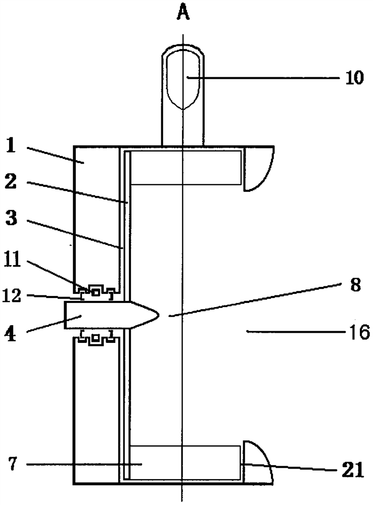
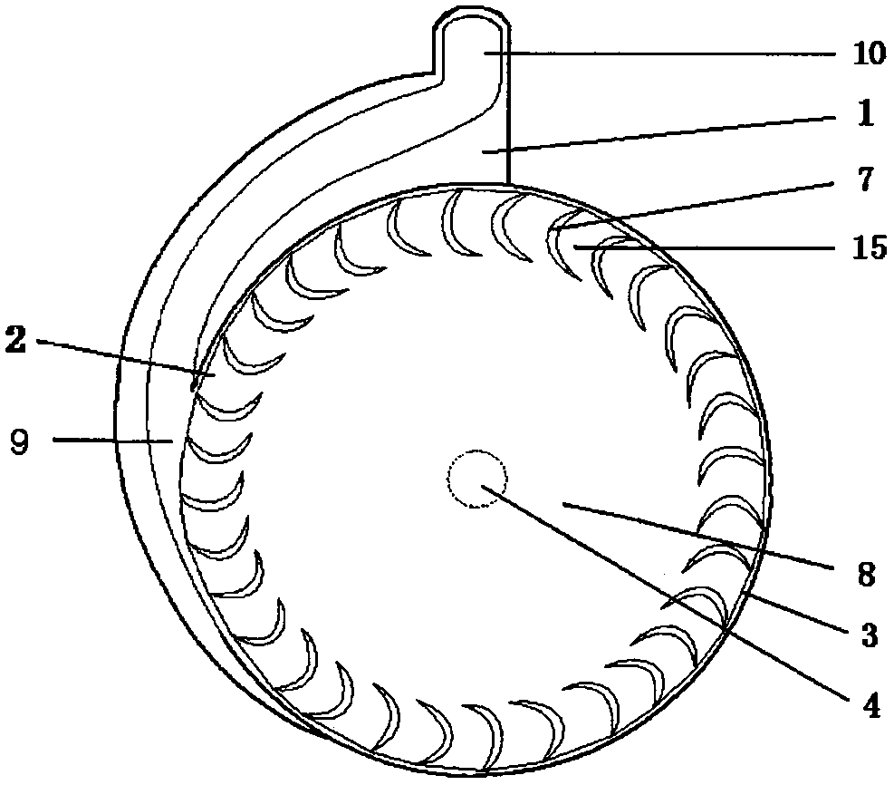
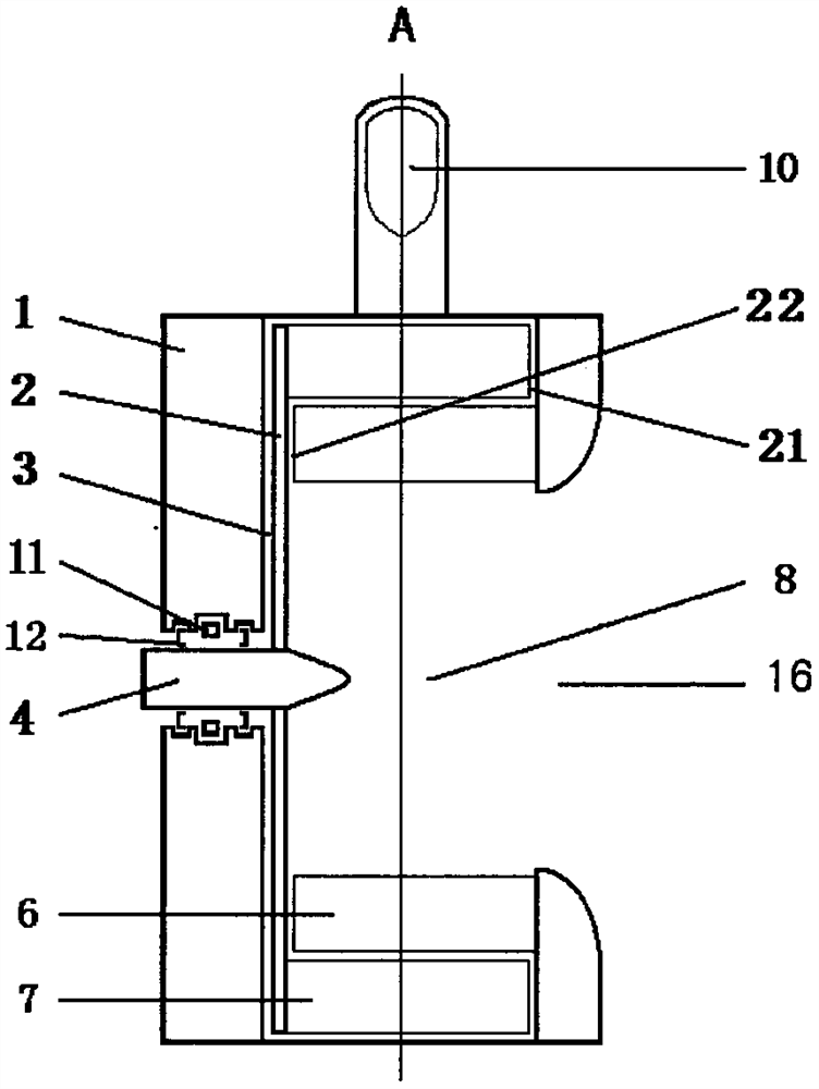
[0031] figure 1 , figure 2 The first embodiment of the novel turbine power device is shown together. As can be seen from the accompanying drawings, the new turbine power device shown in this embodiment is mainly composed of a housing 1, a wheel body 2, a wheel shaft 4, and a basic rotor. , there is a wheel cavity 3 in the housing 1, the wheel body 2 is installed in the wheel cavity 3, the basic rotor is installed on the side of the wheel body 2, the wheel shaft 4 is installed on the center of the wheel body 2, and the wheel shaft 4 and ...


PUM


Abstract

The invention provides a novel turbine acting device. The device comprises a shell, a wheel cavity, a wheel shaft, a rotor, a stator and the like, the shell is provided with an air inlet and an air outlet, the rotor is formed by arranging long-strip-shaped movable blades into a roller shape according to a certain angle, one end of the rotor is installed on a wheel body, the wheel body is fixed to the wheel shaft and installed in an inner wheel cavity of the shell, the stator is formed by arranging long-strip-shaped stator blades according to a certain angle to be in a cylindrical shape, one end of the stator is installed on the inner wall of the wheel cavity opposite to the wheel body, the other end of the rotor is arranged outside the stator in a sleeving manner, and the air inlet is in an involute shape on the circumferential face of the wheel cavity. The air outlet is formed in the center of the circumferential side face of the wheel cavity.

Description

Technical field: [0001] The invention relates to a power machine, in particular to a turbine work device. Background technique: [0002] In the prior art, the prior art closest to this application is the working turbine technology on the turbine engine. Although the turbine engine in the prior art is called the crown in the industry, it belongs to the tip of the tip in the industry, but There are still design flaws, that is, the multi-stage power turbines in the turbine engine are all axially arranged, and the rotating speeds of the power impellers at all levels are basically the same when doing work, and even the diameter of the end power impeller is larger than that of the beginning power impeller. That is to say, in the prior art, the tip speed of the working impeller at the end of the turbine engine is greater than the tip speed of the working impeller at the beginning, so that the flow velocity of the working medium at the end, that is, the high-energy gas, will be equa...

Claims


Application Information

Patent Timeline
IPC IPC(8): F01D5/14F01D9/04F01D25/00F01D25/24
CPCF01D5/141F01D5/147F01D9/041F01D25/00F01D25/24
Inventor 于洁
Owner 于洁
Learn More