Sealing machine cabinet with heat superconducting heat exchanger
A technology of heat exchanger and thermal superconductivity, which is applied in the directions of sealed casing, cooling/ventilation/heating transformation, electrical components, etc., can solve the problems of easy dust accumulation on heat sinks, low heat exchange efficiency, and large air flow resistance, etc., to achieve Unrestricted working environment, high heat transfer efficiency and large heat transfer capacity
- Summary
- Abstract
- Description
- Claims
- Application Information
AI Technical Summary
Problems solved by technology
Method used
Image

Examples
Embodiment 1
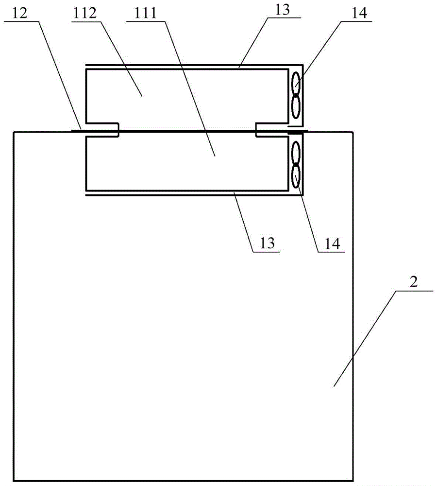
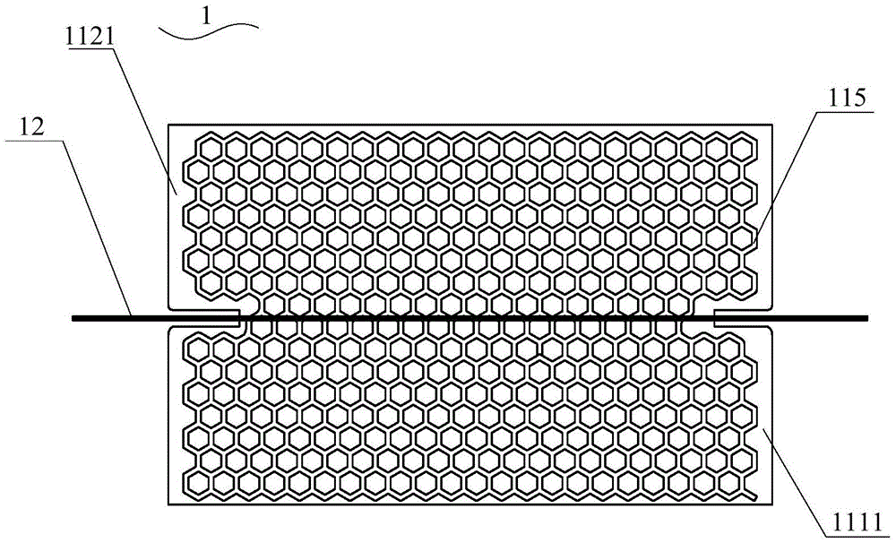
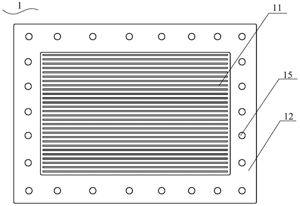
[0063] See Figure 1 to Figure 7 , The present invention provides a sealed cabinet with a thermal superconducting heat exchanger, the sealed cabinet with a thermal superconducting heat exchanger includes: a thermal superconducting heat exchanger 1 and a sealed cabinet 2; wherein, the thermal superconducting heat exchanger The heat exchanger 1 includes a thermal superconducting fin group and a baffle 12; the baffle 12 is located in the middle of the thermal superconducting fin group, and divides the thermal superconducting fin group into a heat absorbing part 111 and a heat releasing part. Part 112, the heat absorption part 111 is located inside the sealed cabinet 2, and the heat release part 112 is located outside the sealed cabinet 2; the partition plate 12 is installed and fixed on the surface of the sealed cabinet 2 to hold the suction While the thermal component 111 is separated from the heat releasing component 112, the inside of the sealed cabinet 2 is completely isolated ...
Embodiment 2
[0082] See Figure 8 to Figure 10 The present invention also provides a sealed cabinet with a thermal superconducting heat exchanger. The structure of the sealed cabinet with a thermal superconducting heat exchanger in this embodiment is the same as the one with thermal superconducting heat in the first embodiment. The structure of the sealed cabinet of the switch is roughly the same. The difference between the two is that the partition 12 in the first embodiment is located on the top of the sealed cabinet 2, and the heat absorption component 111 is located on the top of the sealed cabinet 2. On the inside, the heat dissipating component 112 is located outside the top of the sealed cabinet 2; the shape of the first part 1111 of the thermal superconducting fin is rectangular, and the first part 1111 of the thermal superconducting fin is located in the The inner side of the top of the sealed cabinet 2 and extends from the top of the sealed cabinet 2 to the inside of the sealed cab...
Embodiment 3
[0085] See Figure 11 to Figure 13 The present invention also provides a sealed cabinet with a thermal superconducting heat exchanger. The structure of the sealed cabinet with a thermal superconducting heat exchanger in this embodiment is the same as the one with thermal superconducting heat in the first embodiment. The structure of the sealed cabinet of the switch is roughly the same. The difference between the two is that the partition 12 in the first embodiment is located on the top of the sealed cabinet 2, and the heat absorption component 111 is located on the top of the sealed cabinet 2. On the inside, the heat dissipating component 112 is located outside the top of the sealed cabinet 2; the shape of the first part 1111 of the thermal superconducting fin is rectangular, and the first part 1111 of the thermal superconducting fin is located in the The inner side of the top of the sealed cabinet 2 and extends from the top of the sealed cabinet 2 to the inside of the sealed c...
PUM
 Abstract
Description
Claims
Application Information
 - R&D
- Intellectual Property
- Life Sciences
- Materials
- Tech Scout
- Unparalleled Data Quality
- Higher Quality Content
- 60% Fewer Hallucinations
Browse by: Latest US Patents, China's latest patents, Technical Efficacy Thesaurus, Application Domain, Technology Topic, Popular Technical Reports.
© 2025 PatSnap. All rights reserved.Legal|Privacy policy|Modern Slavery Act Transparency Statement|Sitemap|About US| Contact US: help@patsnap.com