Outer casing for control cable and control cable
A technology for control cables and casings, applied in the field of casings for control cables and control cables, can solve the problems of heavy casings and cannot meet the requirements of light weight, etc., and achieves the effect of improved wiring performance, light weight, easy wiring, and easy manufacturing.
- Summary
- Abstract
- Description
- Claims
- Application Information
AI Technical Summary
Problems solved by technology
Method used
Image

Examples
no. 1 Embodiment approach -
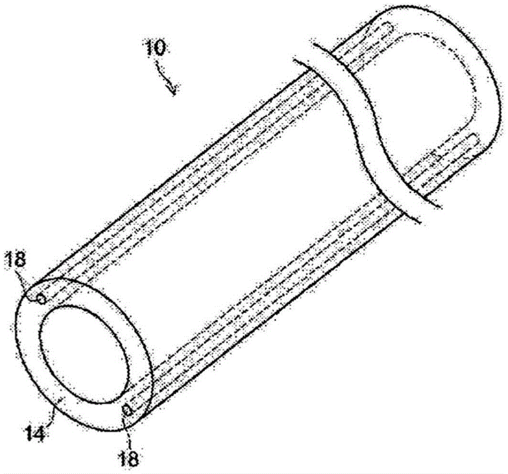
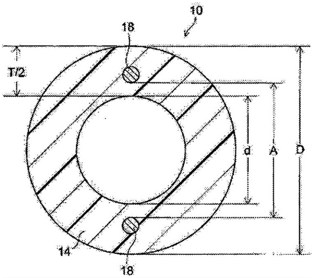
[0045] figure 1 An example (first embodiment) of the configuration of the casing according to the embodiment of the present invention is briefly shown, figure 2 A cross section perpendicular to the axial direction is briefly shown.
[0046] The casing 10 according to this embodiment includes a resin tubular body 14 having a single-layer resin layer formed in a tubular shape, and two resin layers embedded in the resin tubular body 14 at positions parallel to the axial direction and symmetrical with respect to the axis. The outer diameter D (mm) of the resin tubular body 14 and the distance A (mm) between the two metal wires 18 satisfy the above formulas (1) and (2).
[0047] It should be noted that in the present invention, "the interval A between two metal wires" refers to figure 2 The shortest distance between metal wires when two parallel metal wires are viewed in a cross section perpendicular to the axial direction shown is shown.
[0048] Hereinafter, each constituent...
no. 2 Embodiment approach -
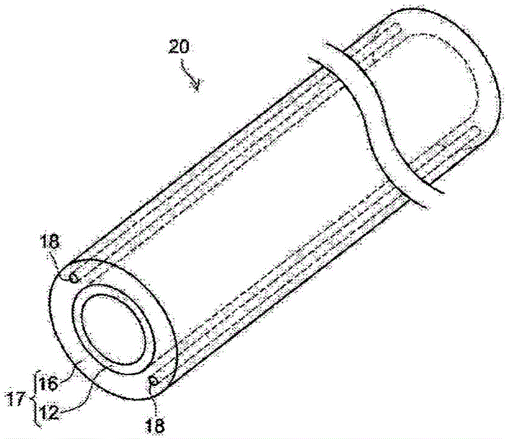
[0071] image 3 Another example of the configuration of the casing according to the embodiment of the present invention (second embodiment) is briefly shown. In the case 20 according to the present embodiment, the resin tubular body 17 has two resin layers 12 and 16, has an outer tubular body (outer resin layer) 16 in which two metal wires 18 are embedded, and is laminated on the outer tubular body. 16 and includes an inner tubular body (inner resin layer) 12 of crystalline resin.
[0072] As in the present embodiment, even when the resin layer of the resin tubular body 17 has a two-layer structure, it may be configured so as to satisfy the above formulas (1) and (2).
[0073] It should be noted that "the difference between the outer diameter and the inner diameter of the resin tubular body" in the case of the present embodiment is the difference between the outer diameter and the inner diameter of the entire resin tubular body, that is, "the outer diameter of the outer tubul...
Embodiment 1
[0134] (Manufacture of single-layer housings incorporating metal wires)
[0135]Resin PP1 pellets were supplied to a crosshead type single-screw extruder (manufactured by Nippon Steel Works Co., Ltd.) with a screw diameter of 30 mm and a length / diameter ratio (L / D)=30 as an extruder. It is extruded into a tubular shape, and at the same time, two hard steel wires are introduced from the rear of the mold to be embedded in the middle part of the wall thickness of the tubular resin tube in a symmetrical position parallel to the longitudinal direction. Thus, a single-layer casing with metal wires was obtained having an outer diameter (D) of 4 mm, an inner diameter (d) of 2 mm, a resin layer thickness (T / 2) of 1 mm, and a distance (A) between metal wires of 2.8 mm.
PUM
| Property | Measurement | Unit |
|---|---|---|
| elastic modulus | aaaaa | aaaaa |
| elastic modulus | aaaaa | aaaaa |
| elastic modulus | aaaaa | aaaaa |
Abstract
Description
Claims
Application Information
 - R&D
- Intellectual Property
- Life Sciences
- Materials
- Tech Scout
- Unparalleled Data Quality
- Higher Quality Content
- 60% Fewer Hallucinations
Browse by: Latest US Patents, China's latest patents, Technical Efficacy Thesaurus, Application Domain, Technology Topic, Popular Technical Reports.
© 2025 PatSnap. All rights reserved.Legal|Privacy policy|Modern Slavery Act Transparency Statement|Sitemap|About US| Contact US: help@patsnap.com