A device, method and system for monitoring a network of fluid-carrying conduits

A technology for monitoring equipment and equipment, which can be used in pipeline systems, water supply pipeline systems, general control systems, etc., and can solve problems such as discoloration, biofilm erosion, and impact.

Active Publication Date: 2016-04-13
IP2IPO INNOVATIONS LTD
View PDF13 Cites 20 Cited by
  • Summary
  • Abstract
  • Description
  • Claims
  • Application Information

AI Technical Summary

Problems solved by technology

In addition, rapid changes in flow velocity increase shear stress along the pipe wall, which leads to sediment resuspension and biofilm erosion
As a result, dynamic hydraulic adjustment also affects water quality, reduces residual chlorine, and causes discoloration and customer complaints

Method used


Image

  • A device, method and system for monitoring a network of fluid-carrying conduits
  • A device, method and system for monitoring a network of fluid-carrying conduits
  • A device, method and system for monitoring a network of fluid-carrying conduits

Examples


Embodiment Construction

[0098] Water transmission and distribution systems are critical infrastructure with a high level of control and severe consequences of failure. Continuous monitoring of loading conditions due to dynamic hydraulic behavior helps maintain the structural strength of infrastructure for aging pipelines and protects water quality. Monitoring and controlling dynamic hydraulic conditions requires new methods and instrumentation for collecting continuous high-frequency time-synchronized data and managing large volumes of data under severe electrical constraints. The monitoring system should also be able to query in near real time and retroactively query the extracted, high-frequency, time-synchronized hydraulic data for any time period. This is particularly useful when blowouts or other failures occur and causal analysis is required to identify failure mechanisms by extracting high-frequency, time-synchronized data before and at the time of system failure.

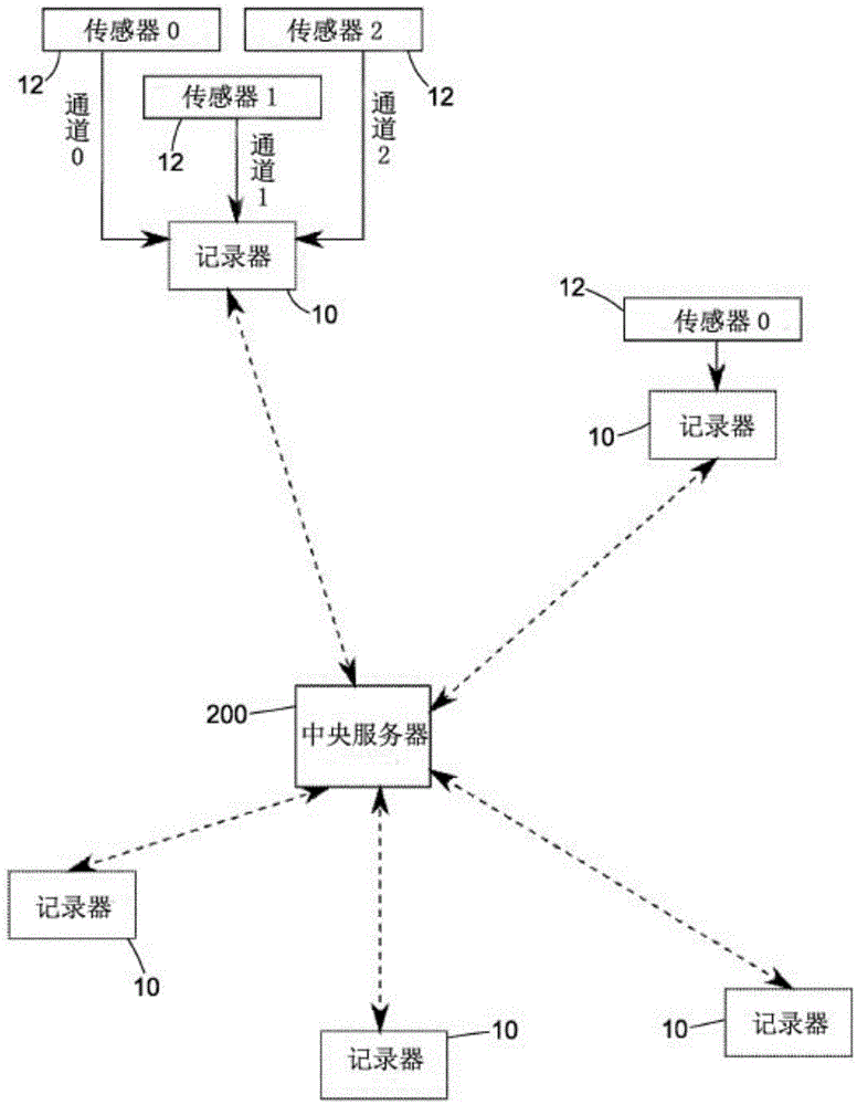
[0099] figure 1 An overvi...


PUM


Abstract

A liquid-flow monitoring device (10) arranged to monitor the flow of liquid in a conduit. The device (10) comprises sampling means (20), processing means (30) and data storage means (40). The sampling means is arranged to receive data substantially continuously from a sensor (12) indicative of at least one variable sensed by the sensor (12) indicative of fluid flow in a conduit and to sample the data to produce a stream of sampled data. The processing means (30) is arranged to process the stream of sampled data to extract at least one sub-sampled stream therefrom, the sub-sampled stream comprising a plurality of data sets, each data set being a statistical subset of the stream of sampled data over a respective data-set period. The data storage means (40) is arranged to store the at least one sub-sampled stream.

Description

technical field [0001] The present invention relates to apparatus and systems, and methods for monitoring fluid flow in pipelines. In an embodiment, the invention relates to monitoring water flow in a water supply system. Background technique [0002] Water systems are sometimes assumed to operate under steady-state hydraulic conditions. In fact, these hydraulic conditions are often quasi-stable and unstable due to randomness in demand, operation of valves, pumps, faulty surge protection devices, and occasional blowouts. This current drive to manage leaks by reducing and controlling operating pressure in near real time may further exacerbate the problem by introducing hydraulic instabilities. Additionally, pump optimization involves switching the pump on and off frequently to reduce energy, resulting in sudden changes in hydraulic conditions. This causes increased tube pressure and associated fatigue failures. These sudden and gradual hydraulic changes cause increased bu...

Claims


Application Information

Patent Timeline
Patent Type & Authority Applications(China)
IPC IPC(8): G01F1/00G05B21/00
CPCG01D4/004G01F1/00E03B7/00Y02B90/20Y04S20/30F17D5/02F17D5/06
Inventor 亚瑟-约翰·霍斯金斯伊凡-约尔丹诺夫·斯托亚诺夫
Owner IP2IPO INNOVATIONS LTD
Why Eureka
Try Eureka