
Internal fixation steel plate for sternoclavicular joint

A technology for fixing steel plates and joints, which is applied in the field of medical devices, can solve problems such as internal fixation failure, sternal transosteal fracture, and enlarged sternal foramen, so as to avoid the enlargement of the sternal foramen, improve the success rate, and avoid the enlargement of the sternal foramen Effect

Active Publication Date: 2016-04-20
林列
View PDF15 Cites 6 Cited by
  • Summary
  • Abstract
  • Description
  • Claims
  • Application Information

AI Technical Summary

Problems solved by technology

However, since the sternoclavicular joint is the only movable joint connecting the upper limb girdle and the body, after a long period of clinical application, it was found that the sternal hole increased to varying degrees and the hook end shifted in different degrees after surgery. Patients with severe osteoporosis and those who did not follow the doctor's advice for early excessive activities may even fracture the sternum through the bone hole, resulting in failure of internal fixation

Method used


Image

  • Internal fixation steel plate for sternoclavicular joint
  • Internal fixation steel plate for sternoclavicular joint
  • Internal fixation steel plate for sternoclavicular joint

Examples


Embodiment 1

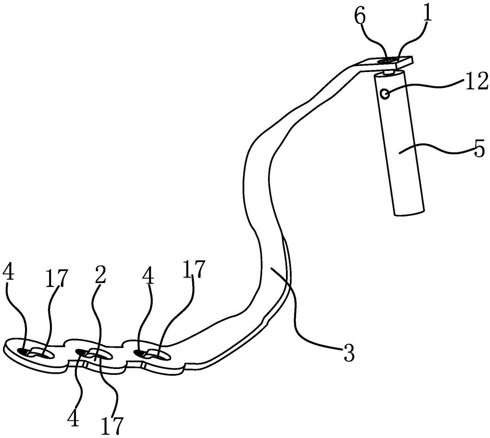
[0034]The internal fixation plate of the sternoclavicular joint includes a positioning rod connection end 1, a clavicle fixing part 2, a transition part 3, a screw hole 4, a sternum positioning rod 5 and a connecting piece 6.

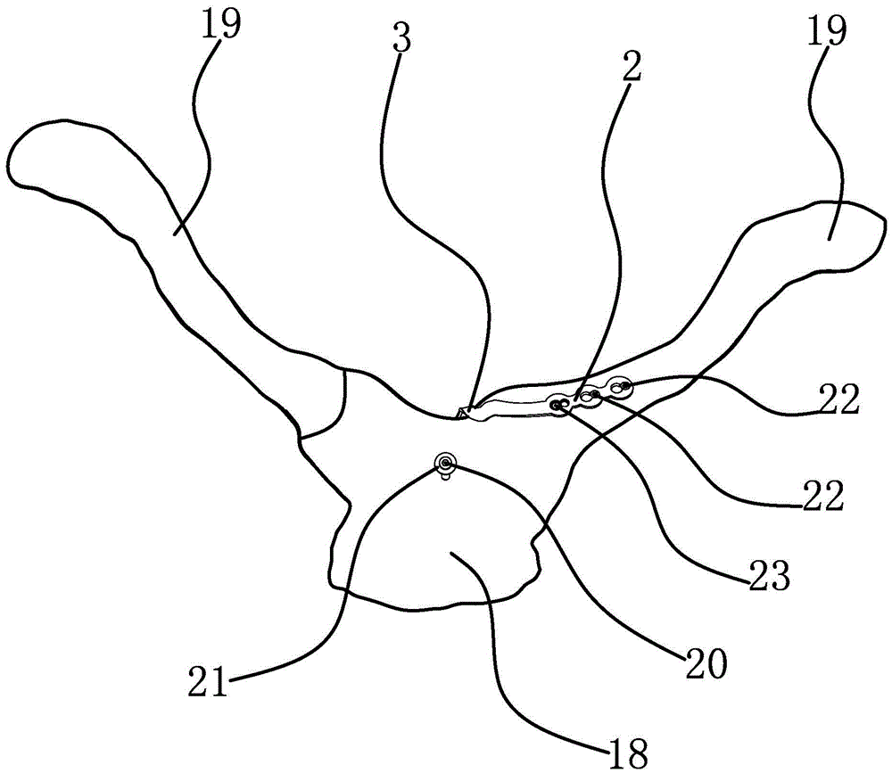
[0035] Specifically, as figure 1 and figure 2 As shown, the cross sections of the positioning rod connecting end 1 and the clavicle fixing part 2 are both flat, the positioning rod connecting end 1 and the clavicle fixing part 2 are not in the same plane, and the positioning rod connecting end 1 and the clavicle fixing part 2 are twisted Shaped transition part 3 is connected. When in use, the connecting end 1 of the positioning rod is located on the sternum 18 , and the clavicle fixing part 2 corresponds to the position of the clavicle 19 .

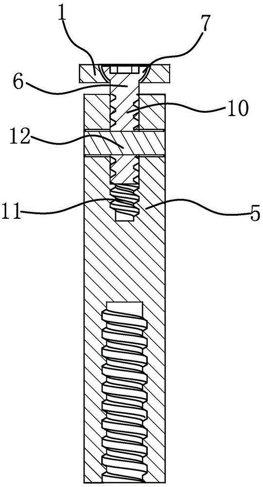
[0036] Such as figure 2 and image 3 As shown, the sternum positioning rod 5 is connected to the positioning rod connecting end 1 through a connecting piece 6. In this embodiment, the connecting piece 6 is cy...

Embodiment 2

[0041] The technical solution in this embodiment is basically the same as the technical solution in Embodiment 1, the difference is that in this embodiment, such as Figure 6 As shown, one end of the connecting piece 6 is fixedly connected to the connecting end 1 of the positioning rod by riveting, and the sternum positioning rod 5 is connected to the other end of the connecting piece 6 through a spherical connection structure. In the actual processing process, the connecting piece 6 can also be fixedly connected with the connecting end 1 of the positioning rod by means of welding, tight fitting and the like.

[0042] In this example, if Figure 6 and 7 As shown, the spherical connection structure includes a ball head 13 located at the end connected to the sternum positioning rod 5 on the connecting piece 6. The end of the sternum positioning rod 5 is petal-shaped and has a spherical hole 14 that matches the ball head 13, preferably three petals or Four petals, the ball head...

Embodiment 3

[0044] The technical solution in this embodiment is basically the same as the technical solution in Embodiment 1, the difference is that in this embodiment, such as Figure 8 As shown, the spherical connection structure includes a ball head 13 located at the end of the connecting piece 6 connected to the sternum positioning rod 5. The end of the sternal positioning rod 5 connected to the connecting piece 6 has a receiving cavity 15, and the receiving cavity 15 has a spherical surface. It is not necessary to cover the entire ball head 13 . In order to prevent the ball head 13 from coming out of the receiving cavity 15 , the sternum positioning rod 5 is also threadedly connected with a screw sleeve 16 . Such as Figure 9 As shown, the screw sleeve 16 has a relief hole 161 for the connecting piece 6 to pass through. In order to allow the ball head 13 to slide in the receiving cavity 15, the sternum positioning rod 5 moves relative to the positioning rod connecting end 1 to give ...


PUM


Abstract

The invention provides an internal fixation steel plate for a sternoclavicular joint, belongs to the technical field of medical instruments, and aims to solve the problems of enlargement of a sternum bone hole and shifting of a hooked end in the conventional internal fixation steel plate for the sternoclavicular joint. The internal fixation steel plate for the sternoclavicular joint comprises a positioning rod connection end and a clavicle fixing part of which transverse sections are flat; the positioning rod connection end and the clavicle fixing part are not in one plane; the positioning rod connection end is connected with the clavicle fixing part through a transition part; the clavicle fixing part has a stripped structure; the clavicle fixing part is provided with a screw hole; the positioning rod connection end is movably connected with a cylindrical clavicle positioning rod through a connecting piece, so that the clavicle positioning rod can rotate and swing relative to the positioning rod connection end. According to the internal fixation steel plate for the sternoclavicular joint, the clavicle fixing part is connected with the clavicle positioning rod through a movable connection structure, so that enlargement of the bone hole due to cutting of the bone hole in the clavicle by the clavicle positioning rod is avoided, and the success rates of surgeries are increased.

Description

technical field [0001] The invention belongs to the technical field of medical devices and relates to an internal fixation steel plate for a sternoclavicular joint. Background technique [0002] Fracture and dislocation of sternoclavicular joint is a common and frequently-occurring disease in clinical practice. Fracture and dislocation of sternoclavicular joint can cause serious complications, even life-threatening. Since the sternum is cancellous bone and the clavicle is located on the anterolateral side of the sternoclavicular joint, Kirschner wires and plates and screws cannot be effectively fixed on the sternum, resulting in poor intraoperative reduction, common postoperative dislocation and pain, and poor curative effect. [0003] In order to perform sternoclavicular arthrodesis better, the applicant once designed a sternoclavicular hook steel plate, and applied for a Chinese patent [application number 200320107941.2; authorized announcement number CN2686545Y] a sternoc...

Claims


Application Information

Patent Timeline
Patent Type & Authority Applications(China)
IPC IPC(8): A61B17/80
CPCA61B17/8014A61B17/8076A61B2017/564A61B17/8061
Inventor 林列
Owner 林列
Learn More