Sterilizing light-emitting tool with heating function and adjustable height

A kind of cutting tool and high-level technology, applied in the field of sterilization light-emitting cutting tools, can solve the problems of poor strength and wear resistance, delayed product production and processing, hard wire insulation, etc., to achieve high strength and wear resistance, safe and reliable use, and smooth incision. smooth effect

Inactive Publication Date: 2016-04-20
倪传华
View PDF3 Cites 0 Cited by
  • Summary
  • Abstract
  • Description
  • Claims
  • Application Information

AI Technical Summary

Problems solved by technology

[0002] At present, cutting tools are made of high-speed steel materials, but high-speed steel materials have poor strength and wear resistance, which makes cutting tools very easy to damage during use, increases the burden on enterprises, and brings greater losses to enterprises.
It takes a lot of time to replace the cutter head, which delays the production and processing of the product
At the same time, the current knives can only be fixed at one height, and the cutting stroke cannot be changed, which cannot meet the cutting requirements of various materials.
In addition, when cutting some products (such as wires), due to the hard insulation of the wires, it is difficult to use direct cutting, which greatly affects the cutting speed and lower cutting efficiency.
At the same time, at present, bacteria are quite easy to remain on the knives, causing the hygienic quality of the knives to be considered, which will also have an adverse effect on the production and processing of the aseptic workshop, and the current knives cannot emit light, so when the light is dark, the operator cannot It is better to use knives, and there are certain safety hazards, which have a greater impact on the operation

Method used


Image

  • Sterilizing light-emitting tool with heating function and adjustable height

Examples


Embodiment Construction

[0013] The present invention will be further described below in conjunction with the accompanying drawings.

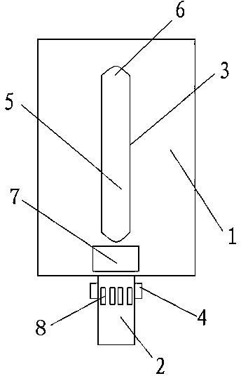
[0014] Such as figure 1 As shown, a sterilizing light-emitting knife with heating function and adjustable height includes a knife body 1 and a knife head 2, and an adjustment installation hole 3 is provided on the knife body 1, and the adjustment installation hole 3 includes a long strip in the middle The hole 5 and the arc hole 6 positioned at both sides of the long hole 5 are provided with a cutter head 2 at the front end of the cutter body 1, and a plurality of heating blocks 4 are connected on the outer edge of the cutter head 2, and the heating block 4 is connected with the heating device. connected, a light source 7 is provided on the tool body 1, the light generated by the light source 7 is ultraviolet light, and several light guide sheets 8 are arranged on the cutter head 2, and the light source 7 and several light guide sheets 8 are located on the same straigh...


PUM

PropertyMeasurementUnit
Lengthaaaaaaaaaa
Lengthaaaaaaaaaa
Lengthaaaaaaaaaa

Abstract

The invention discloses a sterilizing light-emitting tool with a heating function and adjustable height. The sterilizing light-emitting tool comprises a tool body. The sterilizing light-emitting tool is characterized by further comprising a tool bit, wherein a regulating mounting hole is formed in the tool body, wherein the regulating mounting hole comprises a long strip hole in the middle part and circular-arc holes in the two sides of the long strip hole; the front end of the tool body is provided with the tool bit; a plurality of heating blocks are connected on the outer edge of the tool bit; the heating blocks are connected to a heating device; a light source is arranged on the tool body; a plurality of light guide plates are arranged on the tool bit; the light source and the plurality of the light guide plates are positioned on the same straight line; the light guide plates are mutually perpendicular to a cutting edge; the light guide plates are used for absorbing light emitted by the light source, and are used for guiding the light to the cutting edge; and the tool bit is made of a tungsten-titanium-cobalt hard alloy material.

Description

technical field [0001] The invention relates to a cutting tool, in particular to a bactericidal luminous tool with heating function and adjustable height. Background technique [0002] At present, cutting tools are made of high-speed steel materials, but high-speed steel materials have poor strength and wear resistance, which makes cutting tools very easy to damage during use, increases the burden on enterprises, and brings greater losses to enterprises. It takes a lot of time to replace the cutter head, which delays the production and processing of the product. At the same time, the current cutter can only be fixed at one height, and the cutting stroke cannot be changed, which cannot meet the cutting requirements of various materials. In addition, when cutting some products (such as wires), due to the hard insulation of the wires, it is difficult to use direct cutting, which greatly affects the cutting speed and lower cutting efficiency. At the same time, at present, bact...

Claims


Application Information

Patent Timeline
IPC IPC(8): B21F11/00A61L2/10
CPCA61L2/10B21F11/00
Inventor 倪传华
Owner 倪传华
Why Eureka
Try Eureka