Ejection fixing device for milling

A fixing device and milling technology, applied in metal processing equipment, turning equipment, manufacturing tools, etc., can solve the problems of large volume, high machining accuracy and high use cost of automatic fixtures, and achieve simple and compact structure, low machining accuracy requirements, The effect of low production cost

Inactive Publication Date: 2016-04-20
XIAN ZHIYUE ELECTROMECHANICAL TECH
View PDF0 Cites 4 Cited by
  • Summary
  • Abstract
  • Description
  • Claims
  • Application Information

AI Technical Summary

Problems solved by technology

[0002] When using a milling machine to mill parts, the first thing to do is to position and compress the workpiece. At present, there are many ways to tighten the workpiece. Hydraulic and pne

Method used


Image

  • Ejection fixing device for milling

Examples


Embodiment Construction

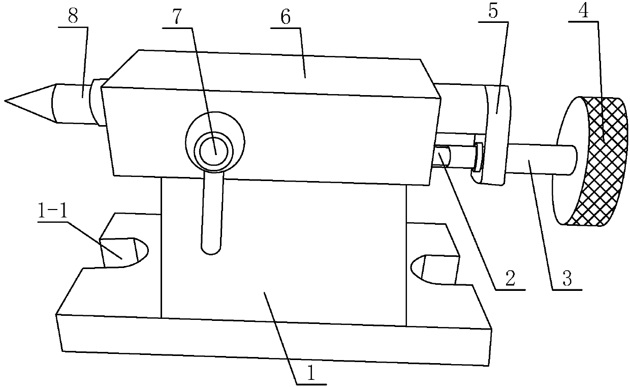
[0020] Such as figure 1 A clamping and fixing device for milling is shown, which includes a mounting base 1 that acts as a fixed support, and also includes a sliding top 8 for clamping the workpiece to be processed and a screw 2 for providing driving force; the mounting base 1 A support 6 is fixedly installed on the upper side, the sliding center 8 is slidably installed in the support 6 through a light hole, and the screw parallel to the sliding center 8 is installed in the support 6 through a threaded hole 2. The tail end of the sliding top 8 is fixedly connected to the upper end of the connecting piece 5, the lower end of the connecting piece 5 is rotatably connected to the rotating shaft 3, one end of the rotating shaft 3 is fixedly connected to the screw 2, and the other end of the rotating shaft 3 is fixedly installed There is a driving handle 4, and the outer peripheral surface of the driving handle 4 is provided with anilox knurling for increasing friction.

[0021] In...


PUM


Abstract

The invention discloses an ejection fixing device for milling. The ejection fixing device for milling comprises a mounting base, a slide tip and a screw rod for supplying driving force; a bracket is fixedly mounted on the upper side of the mounting base; the slide tip is slidingly mounted in the bracket through a polish hole; the screw rod parallel to the slide tip is mounted in the bracket through a thread hole; the tail end of the slide tip is fixedly connected with the upper end of a connecting piece; the lower end of the connecting piece is rotationally connected with a rotating shaft; one end of the rotating shaft is fixedly connected with the screw rod; a driving handle is fixedly mounted at the other end of the rotating shaft; and hatching knurling patterns for increasing friction force are arranged on the outer peripheral surface of the driving handle. The ejection fixing device for milling has the characteristics of good self-locking performance, reasonable design, simple structure, convenience for operation, small size, light weight, convenience for disassembly and maintenance, longer service life, wide application range, low production cost and convenience for promotion and application.

Description

technical field [0001] The invention belongs to the technical field of mechanical processing, and relates to a simple fixture, in particular to a jacking and fixing device for milling processing. Background technique [0002] When using a milling machine to mill parts, the first thing to do is to position and compress the workpiece. At present, there are many ways to tighten the workpiece. Hydraulic and pneumatic automatic clamps are widely used, but the automatic clamps are bulky and inconvenient to disassemble. , High machining accuracy requirements, high cost of use and other shortcomings. Contents of the invention [0003] The purpose of the present invention is to overcome the deficiencies in the above-mentioned prior art, and to provide a jacking and fixing device for milling, which has good self-locking property, reasonable design, simple structure, convenient operation, small size, light weight, and convenient assembly and disassembly. The utility model has the ad...

Claims


Application Information

Patent Timeline
IPC IPC(8): B23B23/04
Inventor 黄冰
Owner XIAN ZHIYUE ELECTROMECHANICAL TECH
Why Eureka
Try Eureka