Brake apparatus

A brake device and brake shaft technology, which is applied to vehicle parts, transportation and packaging, passenger space, etc., can solve the problem of high labor intensity and achieve the effect of reducing labor intensity

Inactive Publication Date: 2016-04-20
宜昌特兰克斯机电设备有限公司
View PDF0 Cites 0 Cited by
  • Summary
  • Abstract
  • Description
  • Claims
  • Application Information

AI Technical Summary

Problems solved by technology

[0002] Some existing mechanical equipment with walking functions, such as milling machines, need to manually control the walking speed during the milling process, which has high labor intensity

Method used


Image

  • Brake apparatus
  • Brake apparatus
  • Brake apparatus

Examples


Embodiment Construction

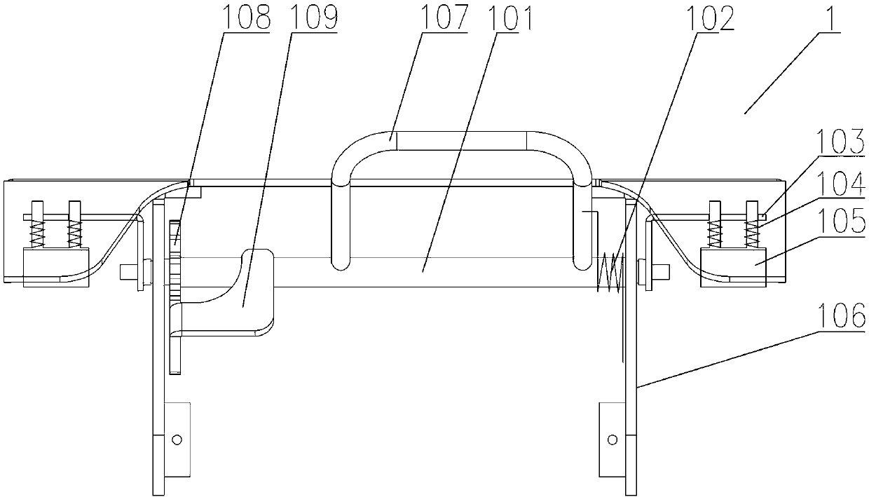
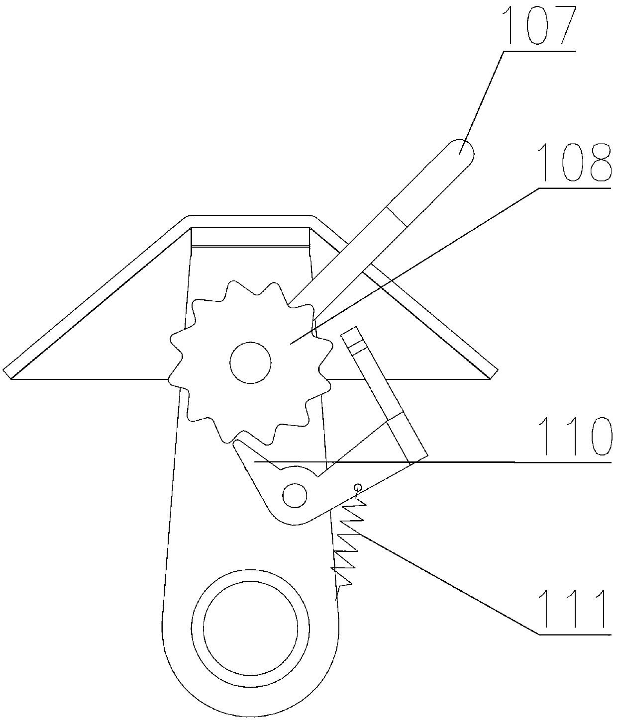
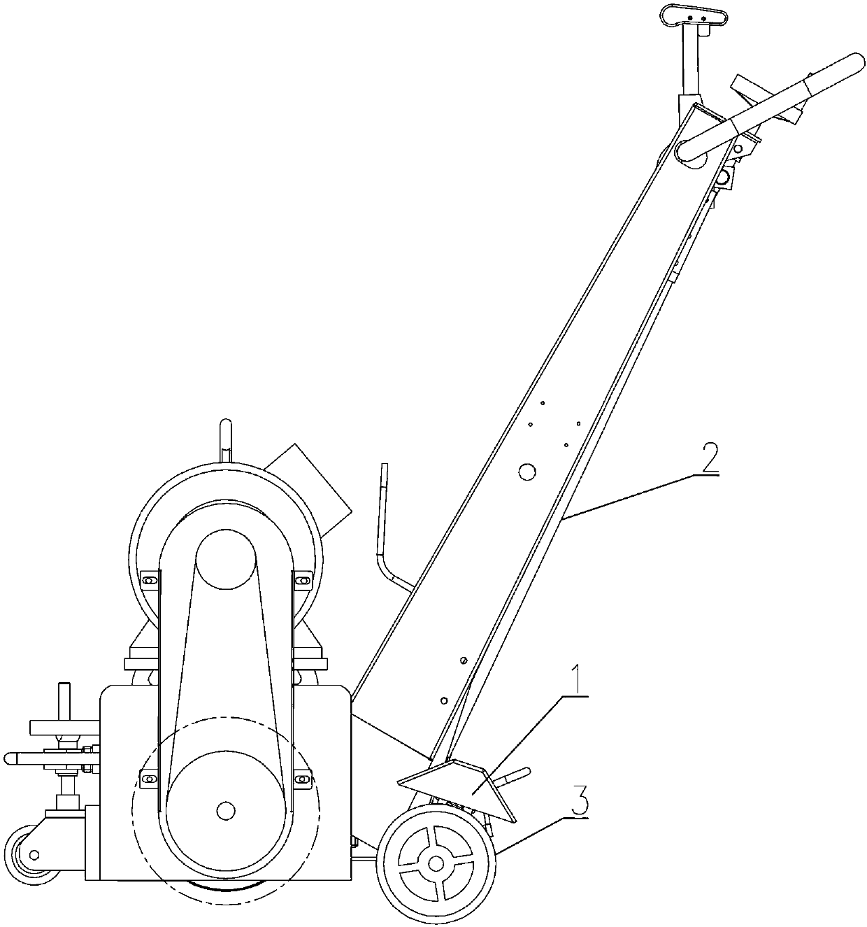
[0014] Such as Figure 1~3 Among them, in the brake device 1, the brake bracket 106 is fixedly connected with the milling machine 2, the brake shaft 101 is pivotally installed on the brake bracket 106, the brake shaft 101 is provided with a pressure handle 107, and the two ends of the brake shaft 101 pass through the brake The seat 103 is equipped with a brake pad 105, and the brake pad 105 is located above the traveling wheel 3;

[0015] A torsion spring 102 is provided between the brake shaft 101 and the brake bracket 106 to make the brake pad 105 tend to separate from the running wheel 3 . Due to the poor construction environment of some mechanical equipment, such as a milling machine, a structure such as a disc brake is easily affected by dust and becomes invalid. Therefore, the structure that directly rubs against the road wheel 3 is less affected by the environment. The brake pad 105 in this example is made of rubber. When in use, the brake pad 105 can be brought into...


PUM


Abstract

Provided is a brake apparatus. A brake support is fixedly connected with a milling machine. A brake axle is installed on the brake support in a pivoted manner. The brake axle is provided with a pressing bar. Two ends of the brake axle are provided with brake pads through a brake base. The brake pads are above a travelling wheel. A torsional spring is between the brake axle and the brake support, so that the brake pads tend to separate from travelling rear wheels. The brake pads are connected with the brake base through a guide rod, and the guide rod is provided with a compressed spring. The brake axle is provided with a ratchet wheel. The brake support is correspondingly provided with a pawl. A tension spring is between the pawl and the brake support. The pawl is fixedly provided with a pedal used to separate the pawl and the ratchet wheel. Through arranging the brake pads on the travelling wheels, the brake apparatus can conveniently adjust travelling speed of a mechanical device, and the brake apparatus is slightly influenced by environment. Through cooperation of the ratchet wheel and the pawl, friction forces between the brake pads and the travelling wheels can be conveniently adjusted, so as to adjust automatic travelling speed of the milling machine, and reduce labor intensity.

Description

technical field [0001] The invention relates to accessories of walking mechanical equipment, such as a brake device for milling machines used for roughening concrete floors, epoxy resin, and wear-resistant surfaces. The invention can also be used on other equipment that needs to control walking speed. Background technique [0002] Some existing mechanical equipment with a walking function, such as a milling machine, need to control the walking speed manually during the milling process, and the labor intensity is relatively high. Contents of the invention [0003] The technical problem to be solved by the present invention is to provide a brake device, which can conveniently adjust the walking speed of mechanical equipment. [0004] In order to solve the above-mentioned technical problems, the technical solution adopted in the present invention is: a brake device, the brake bracket is fixedly connected with the milling machine, the brake shaft is pivotably installed on the ...

Claims


Application Information

Patent Timeline
Patent Type & Authority Applications(China)
IPC IPC(8): B60T1/04B60R7/06
Inventor 魏强魏俊
Owner 宜昌特兰克斯机电设备有限公司
Why Eureka
Try Eureka