
Walking hydraulic transmission system of hydraulic four-wheel-drive high-ground-clearance wheel type spraying machine

A technology of hydraulic transmission and high ground clearance, which is used in fluid pressure actuation system components, motor vehicles, fluid pressure actuation devices, etc., can solve the problems of narrow two-wheel drive application range, high horsepower output loss, and tight operation cycle time. Achieve a wide range of applications, effective transmission, and high horsepower output.

Active Publication Date: 2022-07-12
扬州市职业大学(扬州开放大学)
View PDF17 Cites 0 Cited by
  • Summary
  • Abstract
  • Description
  • Claims
  • Application Information

AI Technical Summary

Problems solved by technology

[0002] In the eastern and western regions of China, high-stem crops such as corn and cotton have become the pillar economic products of agricultural production due to the selection of geographical and climatic reasons; their planting area is very large, and spraying operations need to be carried out regularly during the production cycle. The time is tight, the working environment is very harsh, and the work cannot be done directly by hand, and some high-clearance wheeled sprayers are used
[0003] However, the hydraulic system of the existing high ground clearance wheeled sprayer adopts two drives, which is an open hydraulic system, and has the following defects: 1. The horsepower output loss of the two drives is high
2. The scope of application of the two-wheel drive is narrow, and the muddy and steep areas will affect the stability of the two-wheel drive tractor and the effect of the operation.

Method used


Image

  • Walking hydraulic transmission system of hydraulic four-wheel-drive high-ground-clearance wheel type spraying machine

Examples


Embodiment Construction

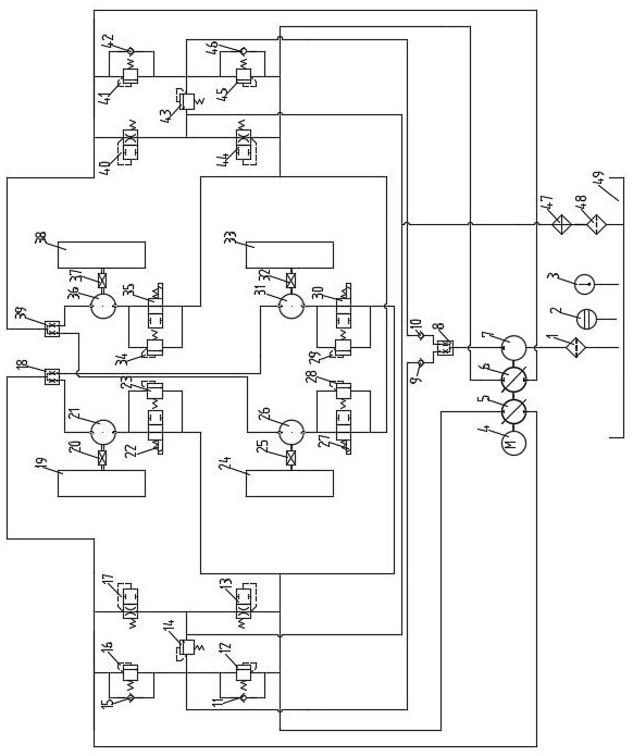
[0013] like figure 1 As shown in the figure, the walking hydraulic transmission system of the hydraulic four-wheel drive high ground clearance wheel sprayer includes a fuel tank 49, an engine 4, a first closed pump 5, a second closed pump 6, a quantitative pump 7, a first diverter valve 18, a first The second diverter valve 39 , the third diverter valve 8 , the left front wheel hydraulic motor 21 , the left rear wheel hydraulic motor 26 , the right front wheel hydraulic motor 36 , and the right rear wheel hydraulic motor 31 .

[0014] The output shaft of the engine 4 is connected to the first closed pump 5 , the second closed pump 6 and the quantitative pump 7 .

[0015] One oil port of the first closed pump 5 is connected to the oil collecting port of the first diverter valve 18, and one oil port of the first diverter valve 18 is connected to the oil port of the left front wheel hydraulic motor 21, and the left front wheel hydraulic motor 21 The other oil port is connected t...


PUM


Abstract

A walking hydraulic transmission system of a hydraulic four-wheel-drive high-ground-clearance wheel type sprayer relates to the field of agricultural machinery and comprises a first closed pump and a second closed pump. One oil port of the first closed pump is connected with an oil collecting port of a first diverter valve, one oil distributing port of the first diverter valve is connected with a left front wheel hydraulic motor and a left front wheel reversing valve, and the other oil distributing port of the first diverter valve is connected with a right rear wheel hydraulic motor and a right rear wheel reversing valve; the right rear wheel reversing valve and the left front wheel reversing valve are connected in parallel and then are connected with the other oil port of the first closed pump; one oil port of the second closed pump is connected with an oil collecting port of a second diverter valve, one oil distributing port of the second diverter valve is connected with a right front wheel hydraulic motor and a right front wheel reversing valve, and the other oil distributing port of the second diverter valve is connected with a left rear wheel hydraulic motor and a left rear wheel reversing valve; and the left rear wheel reversing valve and the right front wheel reversing valve are connected in parallel and then are connected with the other oil port of the second closed pump. The application range of the spraying machine is wider.

Description

technical field [0001] The invention relates to the field of agricultural machinery, in particular to a traveling hydraulic transmission system of a sprayer. Background technique [0002] In the eastern and western regions of China, high-stem crops such as corn and cotton have become the pillar economic products of agricultural production due to the choice of geographical and climatic reasons; the planting area is very large, and spraying operations need to be carried out regularly during the production cycle. The time is tight, the working environment is very harsh, and the work cannot be completed directly by humans, and high ground clearance wheel sprayers are also used. [0003] However, the hydraulic system of the existing high ground clearance wheel sprayer adopts two-wheel drive, which is an open hydraulic system, and has the following defects: 1. The loss of horsepower output of the two-wheel drive is high. 2. The scope of application of the two-wheel drive is narro...

Claims


Application Information

Patent Timeline
Patent Type & Authority Applications(China)
IPC IPC(8): F15B11/17F15B13/02F15B21/041F15B21/0423A01M7/00
CPCF15B11/17F15B13/02F15B13/027F15B21/041F15B21/0423A01M7/0003Y02T10/62
Inventor 陈恒峰王传红张兆东吕宁胡林岚
Owner 扬州市职业大学(扬州开放大学)
Learn More