
Deformation-controllable frame filling wall and construction method thereof

A technology of infill wall and deformation control, applied in the direction of walls, building components, earthquake resistance, etc., can solve the problems of frame column short column failure, strong frame column restraint, "weak layer damage", etc., to enhance the out-of-plane stability and improve the overall Sex, the effect of reducing constraints

Inactive Publication Date: 2016-04-20
INST OF ENG MECHANICS CHINA EARTHQUAKE ADMINISTRATION
View PDF7 Cites 16 Cited by
  • Summary
  • Abstract
  • Description
  • Claims
  • Application Information

AI Technical Summary

Problems solved by technology

[0003] In order to overcome the shortcomings of traditional infill walls, such as high rigidity, strong constraints on frame columns, and unreasonable layout, which may easily cause failure of short columns of frame columns, shear damage of column tops, and damage to "weak floors", and improve the seismic performance of frame-infill wall structures, a new method was proposed. A Deformable Controlled Frame Filled Wall and Its Method

Method used


Image

  • Deformation-controllable frame filling wall and construction method thereof
  • Deformation-controllable frame filling wall and construction method thereof

Examples


Embodiment Construction

[0021] According to the technical solution of the present invention, the anti-seismic structure using the deformation controllable frame filling wall is as follows:

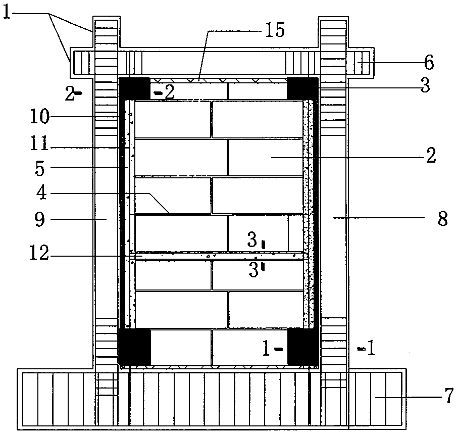
[0022] (1) Make the frame upper beam 6 of the frame 1, the frame lower beam 7 and the frame left column 8, the frame right column 9, and anchor the reinforcing bar of the constraint column 5 in the frame lower beam 7;

[0023] (2) The upper surface of the frame lower beam 7 is chiseled, and the elastic connecting material 15 is laid. The elastic connecting material 15 is bonded firmly with the frame lower beam 7, and the steel bar 11 passing the control part 3 through the restraining column 5 is bonded under the frame. The distance between the end of the beam 7 and the adjacent frame column is not less than 120mm;

[0024] (3) Build upper masonry on the surface of the elastic connecting material 15 and the upper surface of the deformation control part. When building a wall with a height of about 500mm, arrange ho...


PUM


Abstract

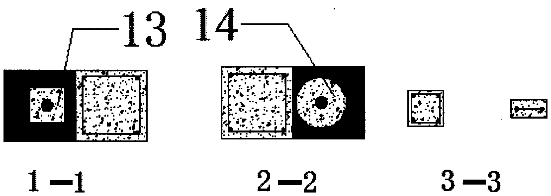
The invention discloses a deformation-controllable frame filling wall which is mainly composed of a frame 1, a filling wall 2, deformation control parts 3, horizontal tie bars 4, restraint columns 5 and horizontal connection beams 12. The deformation-controllable frame filling wall is characterized in that the frame 1 is composed of a frame upper beam 6, a frame lower beam 7, a frame left column 8 and a frame right column 9, the filling wall 2 is a brickwork filling wall which is built by bricks (clay bricks and hollow bricks) or concrete building blocks, the deformation control parts 3 are arranged at positions where four corners of the filling wall contact with joints of the frame, the filling wall 2 is connected with the frame left column 8 and the frame left column 9 through a flexible material 10, and connected with the frame upper beam 6 and the frame lower beam 7 through an elastic connection material 15, the restraint columns 5 are arranged at positions where the filling wall 2 is connected with the flexible material 10, and the horizontal tie bars 4 which are arranged in the height direction of the filling wall are connected with the restraint columns. When the height of the filling wall is large, horizontal tie beams 12 can be arranged in the filling wall, and two ends of the horizontal tie beams 12 are connected with the restraint columns 5.

Description

Technical field: [0001] The invention relates to a deformation-controllable frame filling wall and a method thereof, which belong to the field of building earthquake resistance and disaster prevention. Background technique: [0002] Reinforced concrete frame structure is widely used in commercial and residential buildings, office buildings, hospitals, teaching buildings and hotels, accounting for more than 30% of the total construction in my country. Theory is a more mature structural form. However, RC frame structures have suffered serious earthquake damage in previous earthquakes, especially in the 5.12 Wenchuan Earthquake, a large number of RC frame structures collapsed. In the high-intensity area, the collapse rate was as high as 63%, second only to the highest collapse rate (85%) The bottom frame masonry structure has a collapse rate (48%) that is 15 percent higher than that of the masonry-concrete structure that is generally considered to be weaker in earthquake resist...

Claims


Application Information

Patent Timeline
Patent Type & Authority Applications(China)
IPC IPC(8): E04B2/56E04B2/58E04B2/64E04B1/98E04B2/02
CPCE04B1/98E04B2/02E04B2/56E04B2/58E04B2/64
Inventor 周中一王涛陈永盛
Owner INST OF ENG MECHANICS CHINA EARTHQUAKE ADMINISTRATION
Learn More