
Raised floor

A raised floor and panel technology, applied in the field of building materials, can solve the problems of difficulty in maintenance and inspection construction work, increase costs, time-consuming and labor-intensive, etc., and achieve the effects of simple structure, time saving, and cost reduction.

Inactive Publication Date: 2016-04-20
XINJINWEI NETWORK TECH
View PDF0 Cites 0 Cited by
  • Summary
  • Abstract
  • Description
  • Claims
  • Application Information

AI Technical Summary

Problems solved by technology

However, floor suction cups are generally used in the market to solve the installation of raised floors. This installation scheme brings difficulty to the inspection and construction work, is time-consuming and laborious, increases various costs, and wastes resources.

Method used


Image

  • Raised floor
  • Raised floor

Examples


Embodiment Construction

[0012] Specific embodiments of the invention will be described in detail below in conjunction with the accompanying drawings.

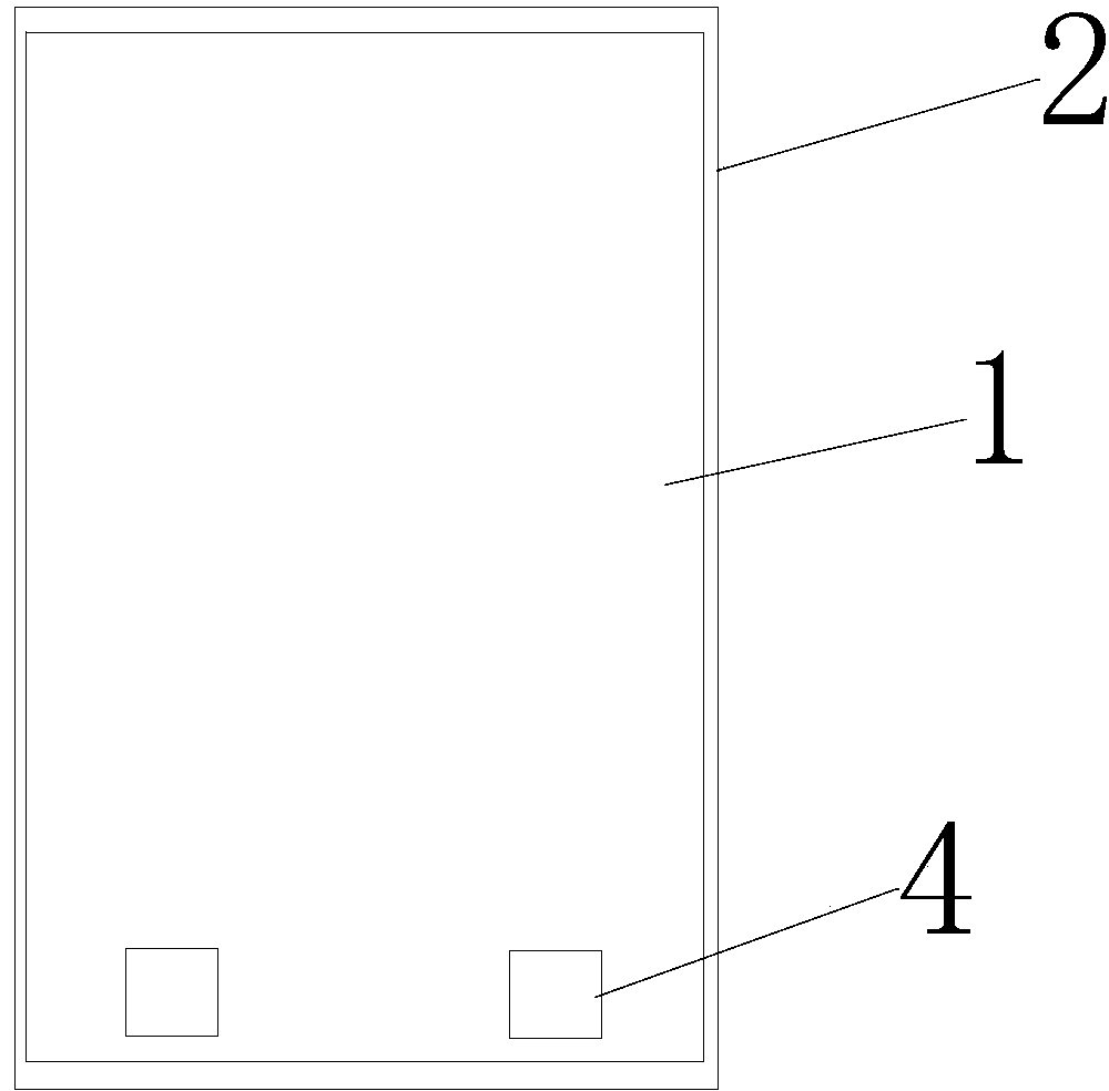
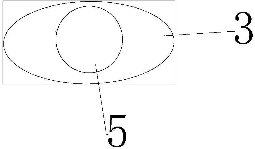
[0013] Such as figure 1 and figure 2 As shown, including the base body, the base body is provided with an upper panel 1, and a bottom plate 2 is provided below, and the position directly in front of the upper end surface of the upper panel 1 is provided with two symmetrically distributed concave grooves 3, through which the concave grooves 3. Open the access floor, a cover plate 4 is arranged above the concave groove 3, and the cover plate 4 is opened and closed by spring control. The cover plate ensures that dust does not fall into the floor, and the concave groove 3 is provided with There are opening holes 5, and the floor body is opened through two opening holes 5, and the distance between the two concave grooves 3 is 80mm-260mm. The diameter of the opening hole 5 is about 80mm, which is in line with the comfort of human fingers, and saves manpo...


PUM


Abstract

The invention provides a raised floor, comprising a base. The base is provided with an upper panel above and a bottom board below, the front of the upper end of the upper panel is provided with two symmetrically distributed grooves, a cover board is arranged above the grooves and can ensure cleanliness, the cover board is controlled through a spring and accordingly is convenient to open and less prone to damage due to abrasion, the grooves are provided with opening holes allowing the floor to be opened by hand and giving operation simplicity, and on the whole, both time saving and consumables cost reduction are achieved.

Description

technical field [0001] The invention belongs to the field of building materials, and in particular relates to a raised floor. Background technique [0002] At present, raised floors are widely used in industrial and mining enterprises, post and telecommunications departments, colleges and universities, electronic computer rooms, carrier computer rooms, microwave communication computer rooms, automatic telephone exchange rooms, office automation computer rooms, ground satellite computer rooms, etc. The raised floor has high quality Lightweight, high strength, smooth surface, good texture, good decorative effect and so on. However, floor suction cups are generally used in the market to solve the installation of raised floors. This installation scheme brings difficulty to the maintenance, inspection and construction work, is time-consuming and laborious, increases various costs, and wastes resources. Contents of the invention [0003] The purpose of the present invention is ...

Claims


Application Information

Patent Timeline
Patent Type & Authority Applications(China)
IPC IPC(8): E04F15/024
Inventor 郝铁乱张永花
Owner XINJINWEI NETWORK TECH
Learn More